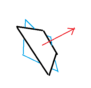
This 3D normalized orientation vector is for the square its normal to the central point of its face for example.
I assume with 'rotation vector' you mean a single direction, e.g. to represent the up axis of an cylinder.
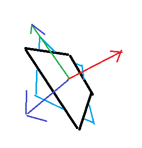
But this is not enough to represent the orientation of an object in 3D, because the object can still rotate about its up axis, and this rotation is then undefined.
The represent orientation think of 3 unit vectors, orthogonal to each other.
You probably know some 3D modeling program or game engine that illustrates those 3 vectors as red, green and blue lines sharing the same origin (the position).
If we use the common representation of an object transform with a 4x4 matrix, the numbers (may) be set like this, for example:
1,0,0, 0 // x axis of the object in worldspace
0,1,0, 0 // y axis of the object in worldspace
0,0,1, 0 // z axis of the object in worldspace
5,4,6, 1 // position of the object in worldspace
The first 3 rows are our 3 axis vectors (followed by a zero)
The 4th row is a point representing the position (followed by a one)
So this is quite intuitive, and after some work of understandig dot product, 3D rotations can be understood geometrically.
I propose you look it up, the first tutorial o found is this: http://www.opengl-tutorial.org/beginners-tutorials/tutorial-3-matrices/
This is a commonly used math library you could use to get started quickly: https://glm.g-truc.net/0.9.9/index.html
To transform a ray into the local space of the object, or to transform reflection back to world space, you need both ‘unrotation’ and ‘rotation’, or ‘inverse transform’ and ‘transfrom’, which usually boils down to matrx - vector multiplication and matrix inversion (which in case of pure rotation is just transpose).
If this all sounds new, focus on dot product which can explain it all.
It is also common to use only a 3x3 matrix for rotations, and handle positions seperately. (For me that's more intuitive)
Quaternions represent orientations with only 4 numbers and make some things easier, e.g. interpolating orientations, or converting to/from axis and angle.
I think axis and angle is the best mind model to think about rotation, while 3x3 matrix is best to imagine orientation.
Differentiating rotation from orientation is similar like differentiating vector form point, although we always can use the same math for both of those.
Euler angles often suck because they are a series of 3 rotations actually, leading to expensive calculations but useful for human interface.
‘Rotation vectors’ are often used in physics simulation, e.g. to model angular velocity or torque. The 3 number describe rotation in radians about the 3 principal axis.
But they only make sense if initial orientation is given, and integrating it requires conversion to axis and angle to update given orientation. It's usually not very useful for geometry applications.