After the Transform matrix converted the vertex position from local/object space to global/world space the view matrix will convert to camera space, is that correct?
The question is: the glm function lookat(eye, at, up) is generating a view matrix or a cameraTranformation matrix?
the eye is the translation of the camera and at is the target of the camera which generates the rotation of the camera, so the translation x rotation of the camera would be cameraTransformation matrix. However in OpenGL I use the lookat to generate the view matrix. So the view matrix is the same thing with cameraTransformation matrix, or is it its inverse matrix, how would that work?
Understanding the view matrix

Author

The view matrix is the inverse of the camera's transformation matrix. You can think of it this way:
- The camera's transform matrix takes something that's local to the camera and transforms it to world space (transforming the point [0,0,0] will give you the camera's position)
- The view matrix takes something that's in world space and transforms it so that it's local to the camera (transforming the camera's position will give you [0, 0, 0])
LookAt functions from math libraries are just a convenience really. If you dig into at how they're implemented, they basically take advantage of the knowledge that a camera's transform matrix only contains position + rotation and uses that to form the inverse of the corresponding transform matrix using a more optimized/direct path than a generalized matrix inverse. In other words, if you were to give them a longer name you could call that function “MakeInverseTransformFromPositionAndForwardDirection”. It's also perfectly valid to form the camera's transform matrix by whatever means you'd like (for example, concatenating a rotation and translation matrix) and then using a general matrix inverse to get the view matrix.
Author
So If I understand correctly:
The view matrix is referred:
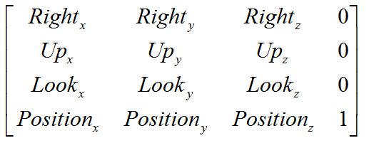
However this is also a formula for view matrix I have seen:
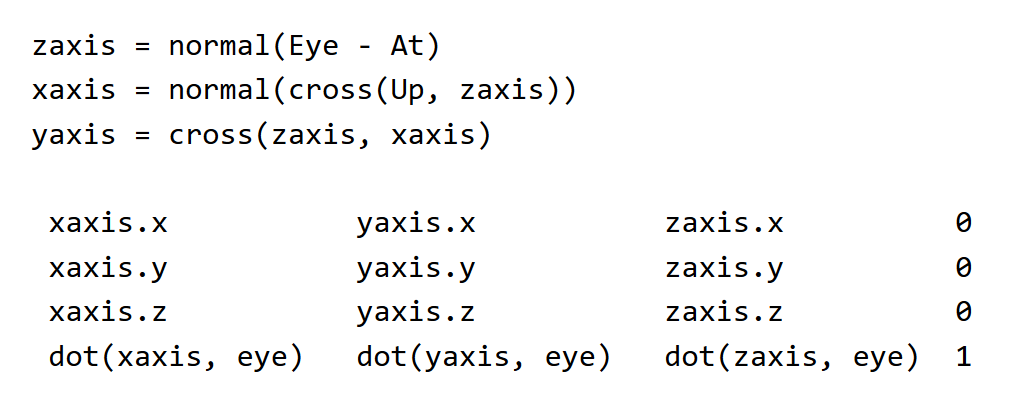
First thing I notice is that the top 4x3 part is identical. The difference is that the bottom row has some vector computation in the second image, where in the first it has the camera's position. And the direction vectors of the top part of the matrix are altered by the parameters eye, at, and up.
I think the fist matrix is for a particular camera matrix where the camera isn't rotated, just positioned. The second matrix is the matrix we need to rotate the view of the camera, is that correct?
For example the lookat function that all API have use the parameters lookat(eye, at, up) by the formulas in the second image to create a view matrix that rotates the view and the camera. The first matrix image is the camera view that hasn't been rotated, it is like I would use the lookat with this parameters: lookat(new Vector3(0, 0, -2), Vector3.Zero, Vector3.Up) where the target is the center of the world so no camera rotation involved. So even if the lookat use the calculation in the second image, the fact that I don't use a rotation makes the result matrix to be similar to the first image where the bottom row is filled with the camera position and the dot products aren't doing anything because I set the at parameter to Vector3.zero. And for the direction vectors the same thing. Because the at is (0, 0, 0) the calcuation at the top of the second image aren't doing anything because of the target being Vector3.Zero the camera isn't rotated and the direction vectors of the camera are the global direction vectors: right(1, 0, 0); forward(0, 0, 1); up(0, 1, 0);
The second thing I want to verify if I understand correctly is that the second image of the view matrix I attached is the inverse of the product of a translation matrix applied to a camera and a roation matrix applied to a camera:
Quaternion rotation = Quaternion.LookRotation(at-eye);
Matrix4x4.Translate(0, 0, -2) * Matrix4x4.Rotate(rotation)
is the inverse of the product equal to the view matrix generated by the second image I attached?

This is an excellent presentation in this context. But a bit more general. Might be helpful…
@bogdan7 That top image looks like standard row-major transformation matrix, where the first 3 rows are the local X/Y/Z basis vectors (AKA the “right”, “up”, and “forward” vectors) and the 4th row is the translation. The second image looks close to a row-major view matrix being formed through a LookAt function, although typically the three dots are negated (like you'd see here). Also the first 3 rows are not identical to the first image: they're actually transposed (the basis vectors are in columns, not rows). If you know how 3x3 rotation matrices work this should make sense: transposing a 3x3 rotation matrix gives you the inverse of that rotation. If you recall a view matrix is the inverse of rotation + translation transform, so this transpose essentially gives you 1 piece of that. Conceptually you can think of that transposed 3x3 part as applying the opposite of the camera's rotation to get thing's into the camera's frame of reference. From there you just need an additional translation that accounts for the camera's position. To get the camera's position in world space you would think of taking the origin (0, 0, 0) and adding the camera's world space position to it as a translation. Now to go the other way you would instead want to subtract the camera's position, except you want to do that in the camera's frame of reference (the space defined by rotating the world by the camera's inverse rotation). You get that by doing those dot products and negating the result, since those dot products are equivalent to multiplying a 3-component vector by the transposed 3x3 rotation.
Author
I think I understood how the matrices I attached are working. What I don't understand is the different namings for view matrix and camera transformation matrix. The view matrix is the one that takes the vertex's position in global space relative to absolute (0, 0, 0) and converts it to be relative to camera's position camera space and I understand from your reply that it can be generated by the lookat function which rotates the camera to point at a specific target similar to the second image I attached or by setting the individual camera's 3 direction vectors similar to the first image I attached. The part of camera transformation matrix I don't get it. Why do we need a matrix to move or rotate the camera if the view matrix already rotates and moves the world where camera wants.
The inverse matrix thing seems pointless:
It is like using:
MVP = ModelMatrix x camera transformationMatrix^(-1) * ProjectionMatrix
instead of:
MVP = ModelMatrix x ViewMatrix x ProjectionMatrix
or saying that the MVP is
modelToWorld x cameraToWorld^(-1) x cameraToClip
instead of
modelToWorld x worldToCamera x cameraToClip
You don't necessarily need to compute or store a camera transformation matrix (or cameraToWorld, in your more explicit terminology). But it can be useful to work that way for doing certain things. For instance it may make your camera controls a lot easier to work with if you first compute a cameraToWorld matrix first and then invert it, since then you can work with your typical rotation and translation operations rather than working in an “inverse” space. Or maybe you have multiple cameras, and it's useful to be able to build a cameraToWorld in order to draw some debug visualization of where the other cameras are in the scene. Or maybe you want to parent some kind off effect (like a particle emitter for rain or snow) to the camera. in which case having the camera's transformation matrix is useful. But that all depends on how your engine works and what exactly you're doing. Ultimately it's just another potential tool in the toolbox.
Author
I think I understand now the view matrix well. We have:
objectSpace      →      worldSpace       →      cameraSpace      →       clipSpace         →         NDC space      →       viewportSpace
           [Model matrix]         [View matrix]         [Projection matrix]    [perspective W division]      [remapping (-1; 1) to screen sizes]
[Model Matrix] = All Object Transofrmations Multiplied(Scale x Rotation x Position) - for row major
[View Matrix] = Inverted LookRotation and position of the camera or setting the Camera Transformation Matrix and inverting it
[Projection Matrix] = Orthographic or Perspective. The oportunity to change fov, clipping planes, aspect ratio
[Perspective division] = take the 3 gl_Positions coordinates and divide them by w to fit them in the NDC cube
[Viewport Remapping] = making the NDC coordinates from [-1, 1] to [0, screen width] and [0, screen height]
Filling the triangles.
This topic is closed to new replies.
Advertisement
Popular Topics

Advertisement