DDA Algorithm Missing Intersections

Started by
9 comments, last by raigan 2 years ago

Hi everyone,

I have tried looking for a solution online and tried a variety of implementations of a DDA algorithm, but none of them seem to give the result I need.

I am programming in Unreal Engine 4, and I generate a 2D grid of 200x200 (UE equivalent to 2mx2m) grid squares over the level. The grid starts at the minimum world XY coordinates for the nav mesh (if one is present) and ends at the max XY extent. The grid size is rounded to the nearest 200 units (so if the minimum X extent is -15680 then it is rounded to -15800 for example). It then generates however many 200x200 grid squares are needed to cover the nav mesh area.

I want to test trace collisions against objects on the grid, and I want to use a DDA algorithm as a means to filter the number of checks. The reason I do this instead of using UE4's default capsule components is because I'm making a Total War type of game where there could be 10k soldiers moving around at once, and 10k moving collision components chokes the engine to a crawl. The basic premise is: iterate through the grid squares intersected by the trace (converted to a 2D line) in order of proximity to the trace origin, and then perform 3D ray-capsule collision checks against any soldiers in those grid squares, ending when a collision is found.

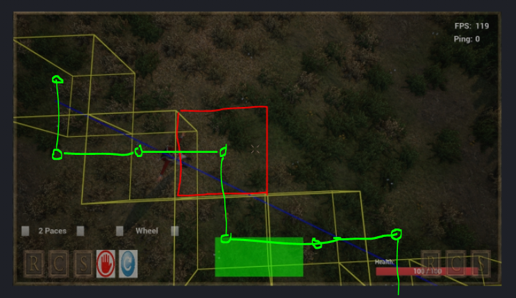
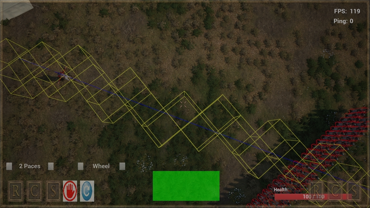
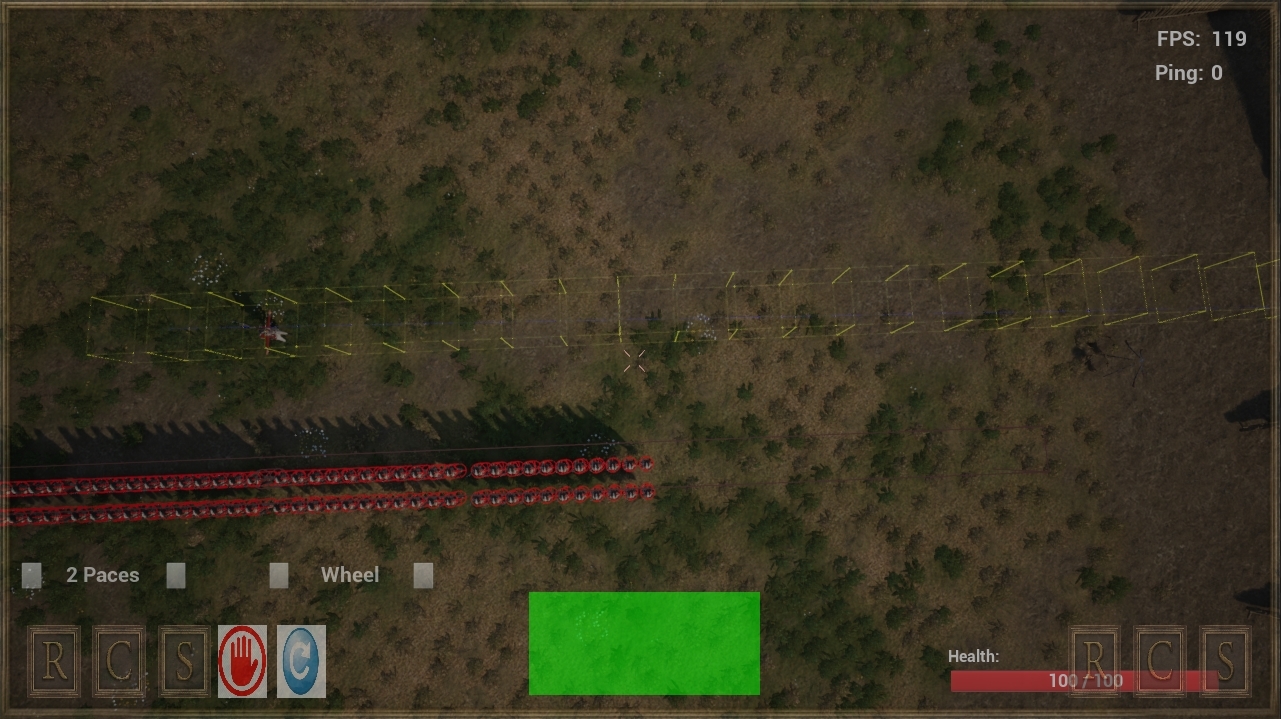
My DDA algorithm isn't quite working however, as you can see below:

https://gyazo.com/9c474ad5c8e2c1dea4edd4360804471f

There are very clear gaps where the blue trace line passes through a grid square but it is not highlighted.

Below is the code I am using:

void ACollisionGridGenerator::TestDDATrace(FVector StartLocation, FVector EndLocation) {
	DrawDebugLine(GetWorld(), StartLocation, EndLocation, FColor::Blue, false, 5.0f, 0, 2.0f);

	// Find the Grid X and Y index for the start of the trace
	double StartIndexX = (double)FMath::FloorToInt(FMath::Abs(MinGridExtents.X - StartLocation.X) * Multiplier);
	double StartIndexY = (double)FMath::FloorToInt(FMath::Abs(MinGridExtents.Y - StartLocation.Y) * Multiplier);

	// Find the Grid X and Y index for the end of the trace
	double EndIndexX = (double)FMath::FloorToInt(FMath::Abs(MinGridExtents.X - EndLocation.X) * Multiplier);
	double EndIndexY = (double)FMath::FloorToInt(FMath::Abs(MinGridExtents.Y - EndLocation.Y) * Multiplier);

	double dx = (double)(EndIndexX - StartIndexX);
	double dy = (double)(EndIndexY - StartIndexY);
	double Step = 0.0f;
	int StepIndex = 1;

	double x, y = 0.0f;

	if (FMath::Abs(dx) >= FMath::Abs(dy)) {
		Step = FMath::Abs(dx);
	}
	else {
		Step = FMath::Abs(dy);
	}

	dx = dx / Step;
	dy = dy / Step;
	x = StartIndexX;
	y = StartIndexY;
	StepIndex = 1;
	FBox CollisionBox;
	while (StepIndex <= Step) {
		int32 CurrGridIndex = (x * NumGridSectionsY) + y;

		DrawGridSquareAtIndex(CurrGridIndex, StartLocation.Z, 5.0f);

		x = x + dx;
		y = y + dy;
		StepIndex++;
	}

}

DrawGridSquareAtIndex is what draws the yellow squares, so as you can see, some grid squares are just missed entirely in the while loop.

Any help would be much appreciated, as I've tried several implementations of DDA and this is the one that comes the closest, but is still not acceptable.

Thanks!

Advertisement

You would typically try a small example with a known result, and walk through the algorithm, checking that each statement computes the example correctly. A debugger would work. You don't even need to draw it, although it may help.

As a random guess, “int32 CurrGridIndex = (x * NumGridSectionsY) + y” looks suspicious to me. Does that work if x and/or y are “random” floating point values? Note the entire right-hand side is computed in floating point, truncating only at the end. EDIT: “2.21 * NumGridSectionsY” may not be what you expect?.

Also, a random site I used for understanding what DDA means at https://medium.com/geekculture/dda-line-drawing-algorithm-be9f069921cf​ says “round Y” in your example, which is not the same as “truncate”.

I remember this problem i think.
There are actually two versions of DDA:
1. If you use it to implement a software rasterizer for example to draw a triangle, missing the one cell like in your picture would be desired, because you do not want to draw clumps of pixels to make an edge, there should be always only one pixel in either horizontal or vertical spans.
2. If you use it for collision detection or other typical uses of tracing, you usually want to get every cell the ray crosses, leading to those clumps of cells where the ray is to cross a span.

Now i can't remember the subtle difference between those two variants in implementation. It's decades ago i've used DDA the last time.
But i do remember it's a detail where tutorials did not help me, and i had too figure it out myself, which was not difficult.
Just follow your code to the missing cell and think about of what should change to process this too. Also make sure you get your cells in the exact order the ray hits them.

Added the missing cell in red to confirm we talk about the same thing:

Hi Alberth and JoeJ,

Thank you for responding so quickly! I think I have got a rough working example which fixes the issue. You are both right: it is an issue with the DDA algorithm by default not being greedy, so it was missing squares by design (yes, JoeJ, your diagram shows the issue with the missing squares). The solution is rounding as you alluded to Alberth. If I write a rough amendment so it does this:

int32 CurrGridIndexMin = (FMath::FloorToInt(x) * NumGridSectionsY) + FMath::FloorToInt(y);

DrawGridSquareAtIndex(CurrGridIndexMin, StartLocation.Z, 5.0f);


int32 CurrGridIndexMax = (FMath::CeilToInt(x) * NumGridSectionsY) + FMath::CeilToInt(y);

DrawGridSquareAtIndex(CurrGridIndexMax, StartLocation.Z, 5.0f);

Now my trace looks like this:

https://gyazo.com/93761911ad640b0f1d56e7d353dc0dac

Which now has the opposite problem, with extra cells being added where not needed, especially if you trace down one of the axes:

https://gyazo.com/fbcfa74066781f3e3a377fbba6332575

So the solution now has to be something that maybe floors by default, and then determines if it needs to ceil as well based on some condition. I'll have a play, but if anyone has any ideas then let me know! Thank you for your input, you were both very helpful ?

I am not sure DDA is the right approach, as you get these gaps. It's probably fixable, but I don't see an easy path currently.

An alternative is to compute where the slow axis reaches the next level, and then add a sequence of blocks at the fast axis up to and including that point.

Alberth said:
It's probably fixable, but I don't see an easy path currently.

I remember it was easy, but not exactly how.

I guess it's something like this:

while (StepIndex <= Step) {
		int32 CurrGridIndex = (x * NumGridSectionsY) + y;


		x = x + dx;
		if (some condition, like rounded x (or y?) having changed from the last iteration) 
			DrawGridSquareAtIndex(CurrGridIndex, StartLocation.Z, 5.0f);
			

		y = y + dy;

		if (some other condition) 

			DrawGridSquareAtIndex(CurrGridIndex, StartLocation.Z, 5.0f);


		StepIndex++;
	}

But this would not ensure correct order. So maybe i used two variants of the loop - one increasing x first, the other y. And it was possible to decide which to use just once before entering the loop.
That's all just guess however. Could not find an example in my old code.

Edit: hmmm… maybe the solution was more like so:

while (StepIndex <= Step) { // need to change this somehow
		int32 CurrGridIndex = (x * NumGridSectionsY) + y;

		DrawGridSquareAtIndex(CurrGridIndex, StartLocation.Z, 5.0f);

		if (some condition)
			x = x + dx;
		else
			y = y + dy;
			
		StepIndex++;
	}

I'm definitively not far off with my proposals.
I did draw the zig zag order we want in green:

The key is: We do not want to skip a corner, and the ray can only cross faces of the cubes, not edges.
The algorithm should be still the same, only with a small modification and minor extra complexity.

It suddenly struck me that Wolfenstein 3D uses a raycasting algorithm like this, which has to be extremely precise so you don't end up with holes in your geometry. This site goes through it:

https://lodev.org/cgtutor/raycasting.html

I'm not at my computer right now, but this might be a good shout to get it working!

Ok, nailed it using that site I found earlier:

void ACollisionGridGenerator::TestDDATrace(FVector StartLocation, FVector EndLocation) {
	DrawDebugLine(GetWorld(), StartLocation, EndLocation, FColor::Blue, false, 20.0f, 0, 2.0f);
	
	FVector RayDir = (EndLocation - StartLocation).GetSafeNormal2D();

	int32 MapX, MapY, GridIndex = 0;
	GetGridIndexForLocation(StartLocation, GridIndex, MapX, MapY);

	int32 EndMapX, EndMapY, EndGridIndex = 0;
	GetGridIndexForLocation(EndLocation, EndGridIndex, EndMapX, EndMapY);

	double sideDistX;
	double sideDistY;

	//length of ray from one x or y-side to next x or y-side
	double deltaDistX = FMath::Abs(1 / RayDir.X);
	double deltaDistY = FMath::Abs(1 / RayDir.Y);
	
	int32 stepX;
	int32 stepY;

	if (RayDir.X < 0)
	{
		stepX = -1;
		double StartXOffset = FMath::Abs(MinGridExtents.X - StartLocation.X) * Multiplier;
		sideDistX = (StartXOffset - MapX) * deltaDistX;
	}
	else
	{
		stepX = 1;
		double StartXOffset = FMath::Abs(MinGridExtents.X - StartLocation.X) * Multiplier;
		sideDistX = (MapX + 1.0 - StartXOffset) * deltaDistX;
	}
	if (RayDir.Y < 0)
	{
		stepY = -1;
		double StartYOffset = FMath::Abs(MinGridExtents.Y - StartLocation.Y) * Multiplier;
		sideDistY = (StartYOffset - MapY) * deltaDistY;
	}
	else
	{
		stepY = 1;
		double StartYOffset = FMath::Abs(MinGridExtents.Y - StartLocation.Y) * Multiplier;
		sideDistY = (MapY + 1.0 - StartYOffset) * deltaDistY;
	}

	// Stop if we reach the square where the trace ends
	while (GridIndex != EndGridIndex)
	{
		DrawGridSquareAtIndex(GridIndex, StartLocation.Z, 20.0f);
		//jump to next map square, either in x-direction, or in y-direction
		if (sideDistX < sideDistY)
		{
			sideDistX += deltaDistX;
			MapX += stepX;
		}
		else
		{
			sideDistY += deltaDistY;
			MapY += stepY;
		}

		GridIndex = (MapX * NumGridSectionsY) + MapY;		

	}

}

The “GetGridIndexForLocation” function just does the same job that I was doing before when calculating StartIndexX and StartIndexY except I bundled all index calculations into one handy function.

Gives a nice, full set of intersections on the angle:

And a nice, solid line along the axis:

For future reference, here's a paper which presents a DDA to visit each cell touched by a ray:

http://www.cse.yorku.ca/~amana/research/grid.pdf

This topic is closed to new replies.

Advertisement