I recently noticed a strange issue with my implementation of the Cook-Torrance specular BRDF, where the specular part of the BRDF will shine through to the back side of a lit object if normal maps are enabled. Below is an example of what this looks like. The camera is underneath a thin box plane looking upward, with a point light source above the plane (located at the center of the bright spot). Ambient and diffuse lighting is disabled.
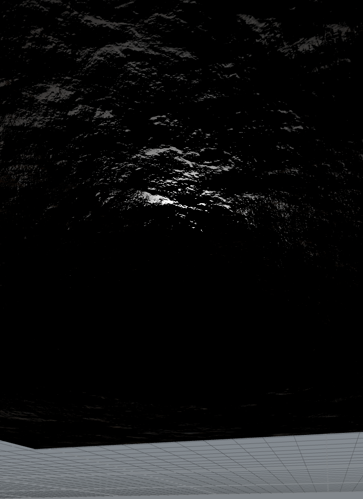
This problem does not occur with either the Phong or Blinn-Phong BRDFs, nor does it occur if I only include the diffuse part of the Cook-Torrance BRDF. It also does not occur if I disable normal mapping, or if shadow mapping is enabled (shadow visibility term cancels it out).
I have double checked that normals look OK by visualizing them in RGB channels. There are no normals on the bottom side of the plane that point up toward the light. I've also checked that all vectors are normalized, and that dot products are clamped to be >0.
I haven't been able to find any mention of this issue anywhere online, and I have checked my shader code against various implementations online and don't see any major differences. My shader code for the Cook-Torrance BRDF looks like this:
void evaluateBRDFCookTorrance( in vec3 lightColor, in vec3 L, in float visibility, in float attenuation, in float ambient )
{
    #if DIFFUSE_LIGHTING || SPECULAR_LIGHTING || AMBIENT_LIGHTING
        float cosL = dot( surfaceNormal, L );
        float dotNL = max( cosL, 0.000001 );
    #endif

    #if AMBIENT_LIGHTING
        ambientAccumulator += lightColor*(ambient * ambientShade(cosL) * attenuation);
    #endif

    #if DIFFUSE_LIGHTING
        // Diffuse Fresnel Term
        float invDotNL = 1.0 - dotNL;
        float invDotNL2 = invDotNL * invDotNL;
        vec3 Fdiff = F0 + (1.0 - F0) * (invDotNL2*invDotNL2*invDotNL);

        diffuseAccumulator += lightColor*(1.0 - Fdiff)*(dotNL*visibility*attenuation);
    #endif

    #if SPECULAR_LIGHTING
        // Compute half vector (L + V)
        vec3 H = normalize( L - surfaceDirection );

        // Compute dot products.
        float dotNV = max( -dot( surfaceNormal, surfaceDirection ), 0.000001 );
        float dotNH = max( dot( surfaceNormal, H ), 0.000001 );
        float dotHV = max( -dot( H, surfaceDirection ), 0.000001 );

        // Geometry term G.
        float G = min( 1.0, min( dotNV, dotNL )*(2.0*dotNH / dotHV) );

        // Normal distribution function D. (Beckmann distribution)
        float dotNH2 = dotNH * dotNH;
        float dotNHR2 = dotNH2 * surfaceRoughness * surfaceRoughness;
        float D = exp((dotNH2 - 1.0)/dotNHR2) / (dotNH2*dotNHR2);

        // Specular Fresnel Term (Schlick approximation).
        // H dot V is correct for microfacet BRDF, even though Schlick specifies N dot V.
        float invDotHV = 1.0 - dotHV;
        float invDotHV2 = invDotHV * invDotHV;
        vec3 Fspec = F0 + (1.0 - F0) * (invDotHV2*invDotHV2*invDotHV);

        // Cook-Torrance Specular BRDF (without Fresnel Fspec, multiplied below)
        float specularBRDF = (D * G) / (4.0 * dotNV * dotNL);

        specularAccumulator += (lightColor*Fspec) * (dotNL*specularBRDF*visibility*attenuation);
    #endif
}
The main source of the strange specular highlights is the “specularBRDF” term. If I set that equal to 1, then the highlights are not there.
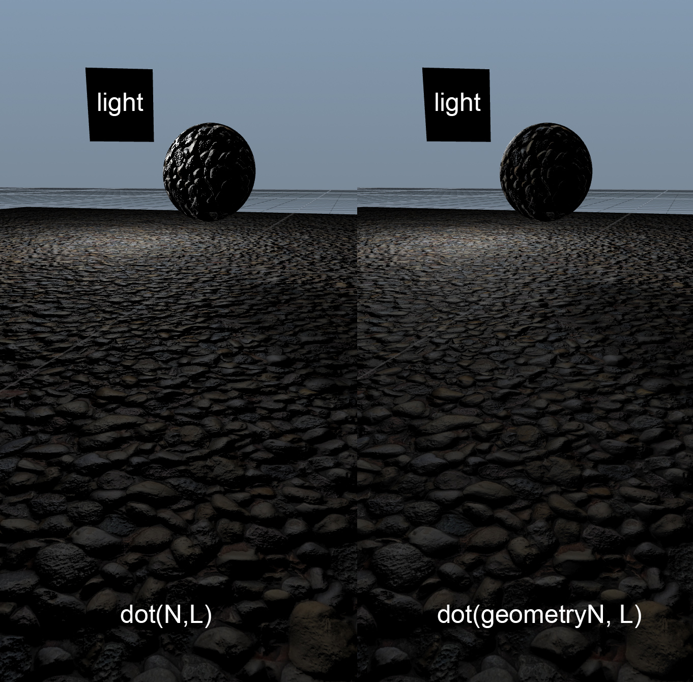
One thing I tried which seems to work OK is to change the “dotNL” (cos(theta)) term of the final line (but not other uses) so that it uses the interpolated vertex normals instead of the “surfaceNormal” which is modified by the normal map. This cancels out the weird specular on the back side of objects, but it also seems like it's not the correct thing to do because it ignores the normal map. It also seems to make the normals look more “flat”, as you can see in the following comparison.
Does anyone have any ideas how to fix this problem in the correct way? Do I have some error in my geometry term G?