
I recently took an interest in sphere topologies to find which one is the best. The most popular one seems to be the fibonacci sphere, so I found some code from here https://stackoverflow.com/questions/9600801/evenly-distributing-n-points-on-a-sphere/26127012#26127012
and then ran it through an AI to convert the code to C and then do some optimizations
#include <math.h>
#include <stdio.h>

#define MAX_POINTS 1000

void fibonacci_sphere(int samples, float points[][3]) {
    /*
    Generates points on a sphere using Fibonacci spiral sampling.

    :param samples: Number of points to generate.
    :type samples: int
    :param points: Array to store generated points.
    :type points: list of lists
    :raises TypeError: If samples is not an integer or points is not a list of lists.
    :return: None
    */

    // Validate inputs
    if (samples <= 0) {
        printf("Number of samples must be a positive integer.\n");
        return;
    }
    if (points == NULL) {
        printf("Points array cannot be NULL.\n");
        return;
    }

    // Calculate golden angle in radians
    float phi = M_PI * (sqrtf(5.0) + 1.0);

    // Generate points on sphere
    for (int i = 0; i < samples; i++) {
        // Calculate y coordinate
        float y = 1.0 - ((float)i / (float)(samples - 1)) * 2.0;

        // Calculate radius at y
        float radius = sqrtf(1.0 - y * y);

        // Calculate golden angle increment
        float theta = phi * i;

        // Calculate x, y, and z coordinates of point
        float x = cosf(theta) * radius;
        float z = sinf(theta) * radius;

        // Store point in points array
        points[i][0] = x;
        points[i][1] = y;
        points[i][2] = z;
    }

    // Log number of points generated
    printf("%d points generated on sphere.\n", samples);
}
which then outputs this
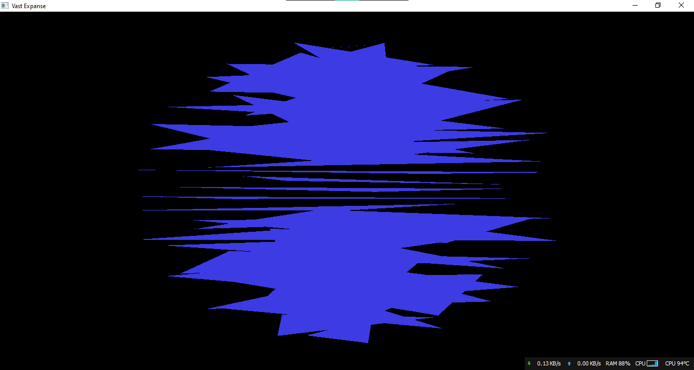
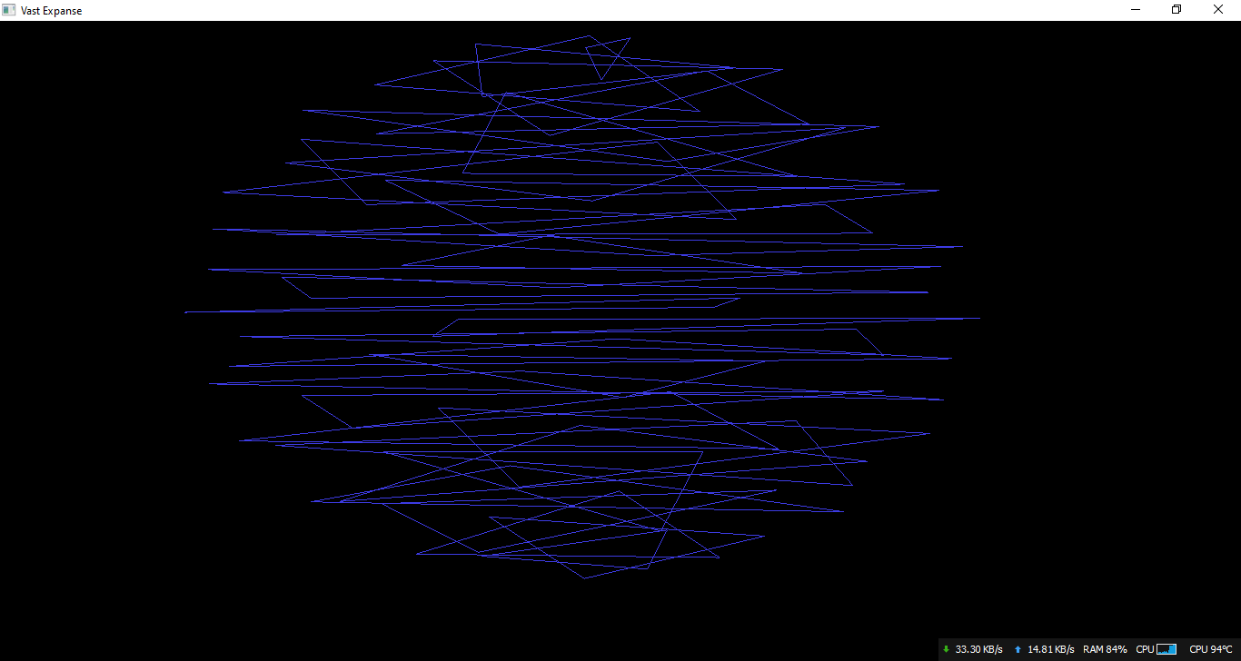
And as you can see, these are unorganized right now, but when I normalize the vertices, I get this

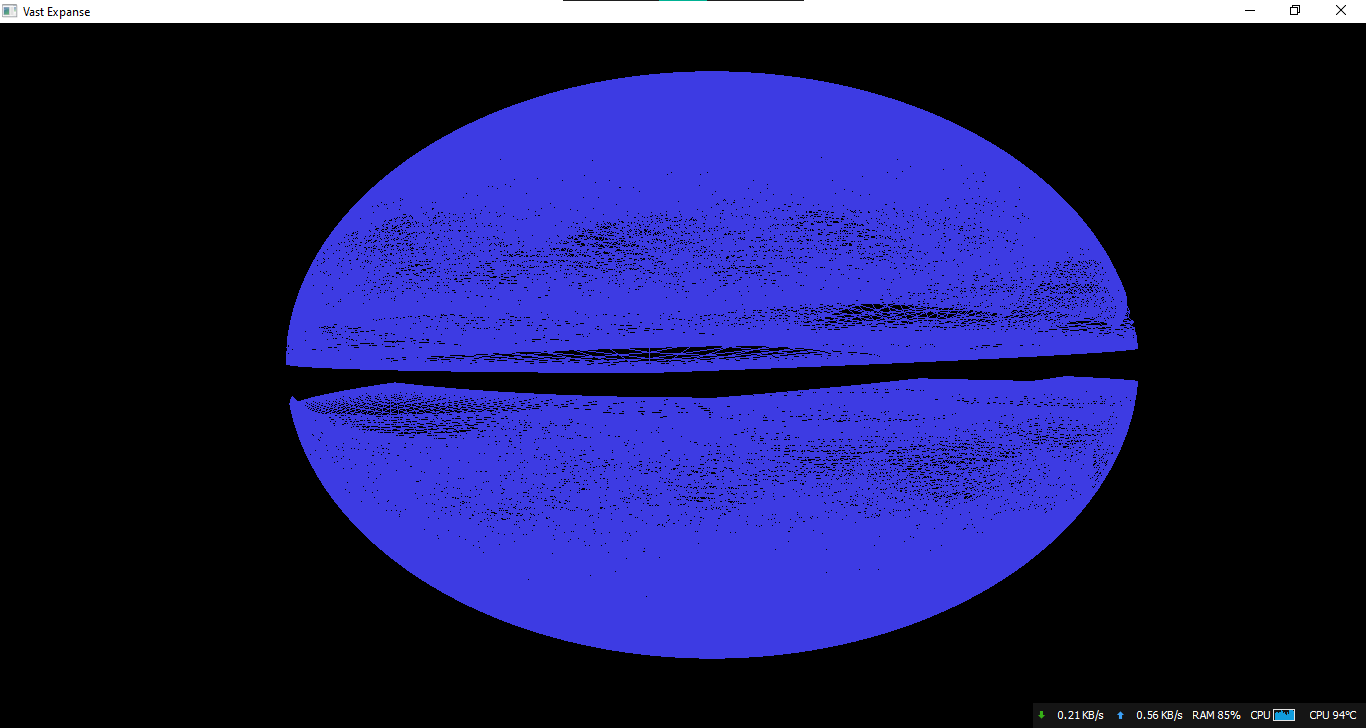
It is a sphere, but it's a little uneven, and plus there is a major gap down the middle, with a bunch of triangles stacking on top of each other unnecessarily.
Here's the rest of my relevant code, starting with the application of the Fibonacci function, and then my tessellation shaders
float vertices[100][3];
fibonacci_sphere(100, vertices);

unsigned int vbo, vao;
glGenVertexArrays(1, &vao);
glGenBuffers(1, &vbo);

glBindVertexArray(vao);

// upload vertex data to gpu
glBindBuffer(GL_ARRAY_BUFFER, vbo);
glBufferData(GL_ARRAY_BUFFER, sizeof(vertices) * sizeof(double), &vertices[0], GL_STATIC_DRAW);

// position attribute
glVertexAttribPointer(0, 3, GL_FLOAT, GL_FALSE, 3 * sizeof(float), (void*)0);
glEnableVertexAttribArray(0);

// normal attribute
glVertexAttribPointer(1, 3, GL_FLOAT, GL_FALSE, 3 * sizeof(float), (void*)(3 * sizeof(float)));
glEnableVertexAttribArray(1);

// amount of tessellation to do per triangle
glPatchParameteri(GL_PATCH_VERTICES, 3);
glBindVertexArray(vao);
glDrawArrays(GL_PATCHES, 0, 100);
#version 450 core
// tessellation control
// specify control points per output per patch
// control size of input and output arrays
layout(vertices=3) out;
// input from vertex shader
in vec3 vert_coord[];
// output to evaluation shader
out vec3 vertex_coord[];
// for dynamic LOD (level of detail)
uniform mat4 view;
uniform mat4 model;
void main()
{
// pass attributes through
gl_out[gl_InvocationID].gl_Position = gl_in[gl_InvocationID].gl_Position;
vertex_coord[gl_InvocationID] = vert_coord[gl_InvocationID];
// control tessellation
if(gl_InvocationID==0)
{
// dynamic LOD (from the learnopengl.com website)
// first: define rendering constants to control tessellation
const float MIN_TESS_LEVEL = 4;
const float MAX_TESS_LEVEL = 64;
const float MIN_DISTANCE = 20;
const float MAX_DISTANCE = 800;
// second: transform each vertex into each eye
vec4 eye_space_pos_1 = view * model * gl_in[0].gl_Position;
vec4 eye_space_pos_2 = view * model * gl_in[1].gl_Position;
vec4 eye_space_pos_3 = view * model * gl_in[2].gl_Position;
// third: distance from camera scaled between 0 and 1
float distance_1 = clamp((abs(eye_space_pos_1.z)-MIN_DISTANCE)/(MAX_DISTANCE-MIN_DISTANCE), 0.0, 1.0);
float distance_2 = clamp((abs(eye_space_pos_2.z)-MIN_DISTANCE)/(MAX_DISTANCE-MIN_DISTANCE), 0.0, 1.0);
float distance_3 = clamp((abs(eye_space_pos_3.z)-MIN_DISTANCE)/(MAX_DISTANCE-MIN_DISTANCE), 0.0, 1.0);
// fourth: interpolate edge tessellation level based on closer vertex
float tess_level_1 = mix(MAX_TESS_LEVEL, MIN_TESS_LEVEL, min(distance_3, distance_1));
float tess_level_2 = mix(MAX_TESS_LEVEL, MIN_TESS_LEVEL, min(distance_1, distance_2));
float tess_level_3 = mix(MAX_TESS_LEVEL, MIN_TESS_LEVEL, min(distance_2, distance_1));
// fifth: set the corresponding outer tessellation levels
gl_TessLevelOuter[0] = tess_level_1;
gl_TessLevelOuter[1] = tess_level_2;
gl_TessLevelOuter[2] = tess_level_3;
// sixth: set the inner tessellation levels
gl_TessLevelInner[0] = max(tess_level_2, tess_level_1);
gl_TessLevelInner[1] = max(tess_level_1, tess_level_3);
}
}
// tessellation evaluation
#version 450 core
// determines what type of tessellation to do
layout(triangles, equal_spacing, cw) in;
// input from control shader
in vec3 vertex_coord[];
// output vec
out vec3 vert;
// allows for object transformations
uniform mat4 model;
uniform mat4 view;
uniform mat4 projection;
void main()
{
// gets barycentric coordinates from the triangles
vec3 u = gl_TessCoord.x * vertex_coord[0];
vec3 v = gl_TessCoord.y * vertex_coord[1];
vec3 w = gl_TessCoord.z * vertex_coord[2];
// makes every triangle an equal distance from the center (that's how spheres are formed)
vec3 pos = normalize(u + v + w);
// output tessellated shape
gl_Position = projection * view * model * vec4(pos, 1.0);
}


