Changes to my BRDF calculations

Started by
6 comments, last by RobM 9 months ago

I've been tinkering with my game engine for some time now (feels like nearly 20 years) and a few years ago I implemented PBR with Image Based Lighting. I was kind of happy with it for a while but something really bugged me with the specular highlights. I put it aside whilst I worked on other things like animation and material creation (I'll follow this topic up with some posts on that).

The other day, I'd had enough, I wasn't happy with my specular highlights so I set about trying to understand the math behind the BRDF calculations. A night spent with ChatGPT had armed me with a lot more understanding of the different components involved and this helped me to figure out what it was that was irritating me.

A few years ago, I tinkered with the material system in Unreal 4 and if you have a simple sphere with a shiny plain material, the specular highlight, when seen at glancing angles looked wrong to me, it was circular instead of wrapping itself around the curve of the sphere. I did make a post about this back in 2015 (https://gamedev.net/forums/topic/670910-pbr-specular-brdf/?page=1).

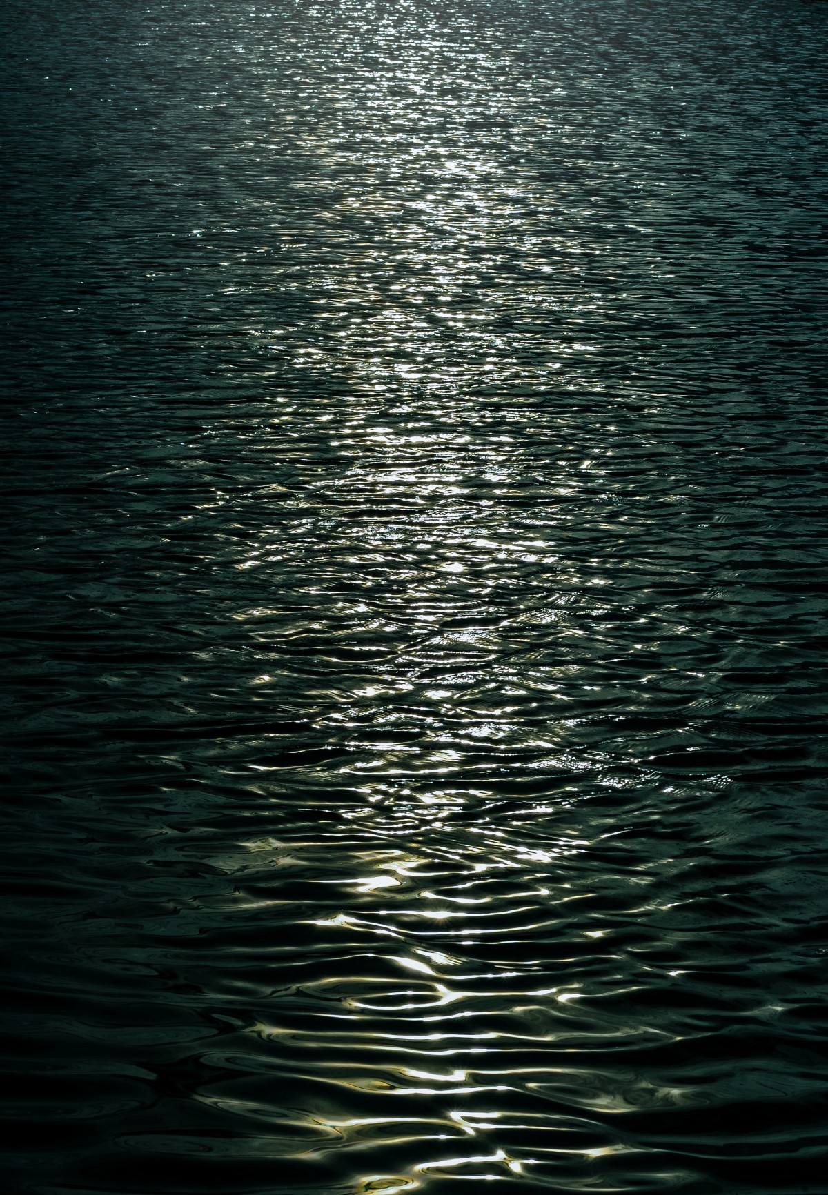
I think it was done this way in order to help with the specular reflections at grazing angles, i.e. to give that long specular reflection you see with car lights on a wet road or the sun setting low over the sea. Either way, both looked wrong.

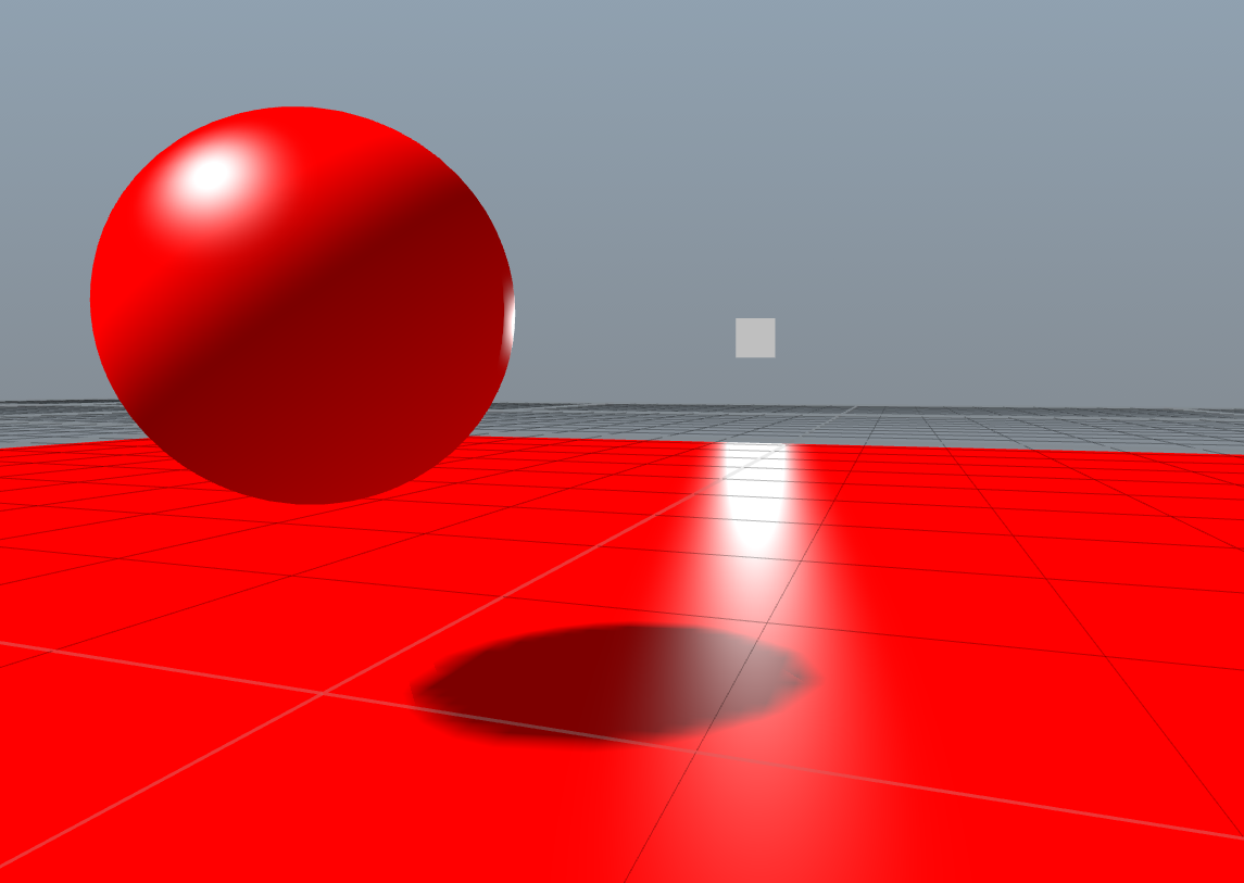
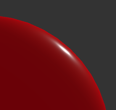
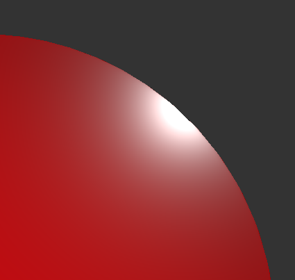
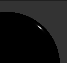
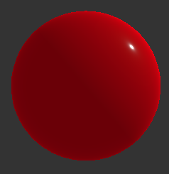
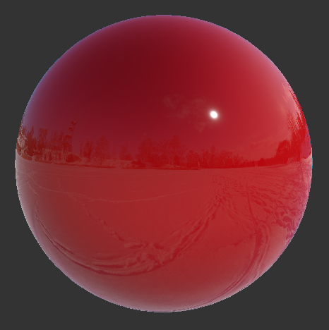
What I found with the BRDF I was using (which was fairly standard I think), was that the Distribution function was using the surface normal dotted with the half vector as its input. Having spent a few hours trying to draw pictures and visualise the various vectors in my head, this didn't seem physically right. So I changed mine to what I thought seemed more physically plausible which was to use a reflection vector from the incident (eye vec) about the normal and to dot that with the light. What this actually gave me was exactly what I was looking for, this:

Using dot(reflect(incident, normal), light)

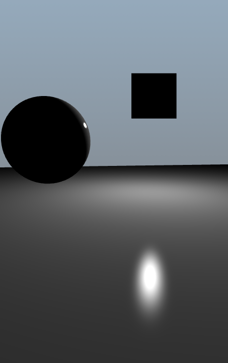
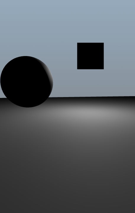
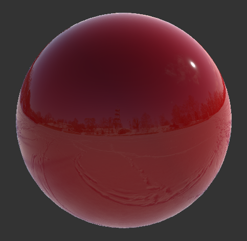
..rather than this (using half vector):

Using dot(normalize(incident, light), light)

I thought maybe this was just my implementation but when I checked Unreal 4, it looked like it was using the half vector too in its implementation as it also had this circular, non curved lobe.

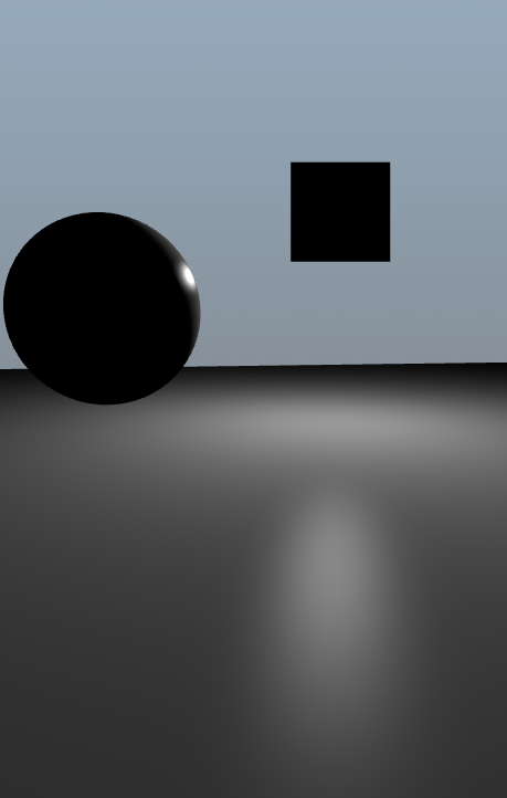
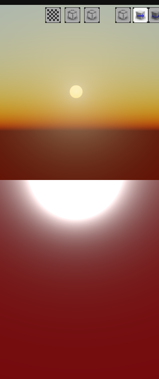
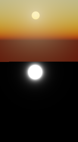
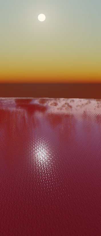
This was all well and good, but I ended up with terrible problems when the sun was at glancing angles on a flat surface. The specular lobe would grow and shrink and give really inaccurate results:

I believe this had to do with the fact that the numerator for the BRDF algorithm is essentially D x G x F and whilst the Distribution function was fine:

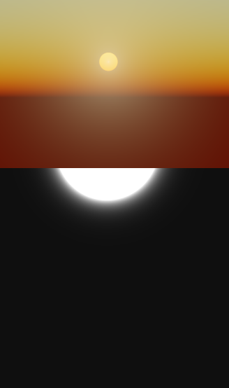
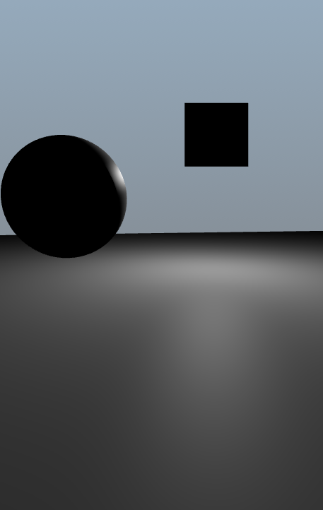
Multiplying in the Fresnel was essentially causing the specular lobe to get bigger at glancing angles. What I really wanted was a consistent lobe at any angle regardless of Fresnel, but that meant taking out the Fresnel calc (and adding it later). From examining the various components of the BRDF, I knew that the Fresnel term basically gives something like this:

Fresnel term for sphere
Fresnel term for flat surface at glancing angle

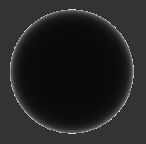
And I could see that this would just increase the Normal Distribution Function result for the specular lobe. What's not easy to see is that the black area at the centre of the sphere, i.e. at viewing angles close to the surface normal, is not 0, it's something like 0.04 or whatever the constant is, typical Fresnel values. So what about if I just multiply the D and G terms by the constant 0.04, which brings my specular lobe to this (this is essentially returning D x G x 0.04):

D * G * 0.04
Very consistent at both high and glancing angles

So then I realised I can't not have any Fresnel so I started looking at where I could add it in. The denominator component (4 * dot(normal, incident) * dot(normal, light)) was something I played with but didn't look right. I then took it out completely and just added my fresnel in using 1 + F whilst calculating the indirectDiffuse (or just diffuse for non-IBL):

Not looking too bad and when I switch on IBL:

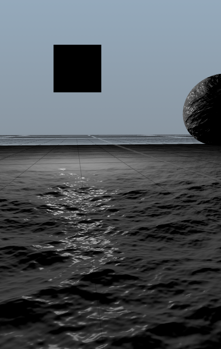
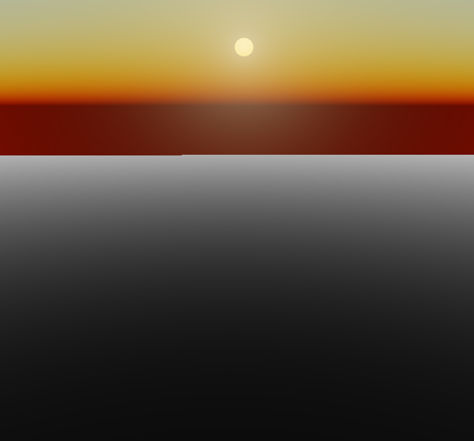
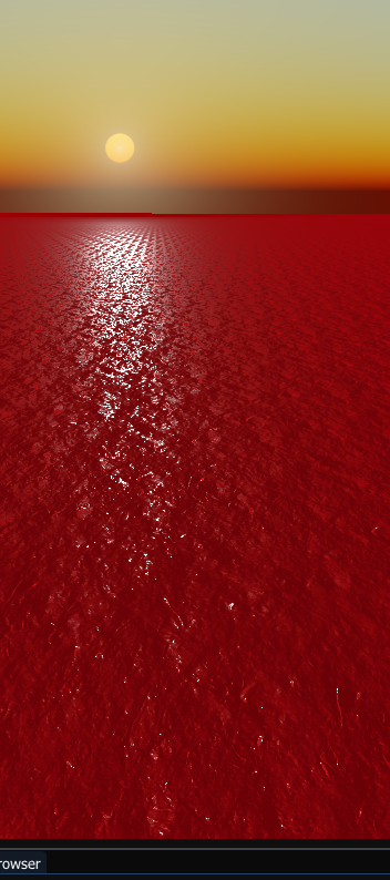
Also looking pretty good. So what about the glancing angle with bumpy material long trail effect that I've longed for and never got:

Looking promising…
Looks physically correct (to my eyes at least)
IBL switched off - looking good
Directly above looking pretty good

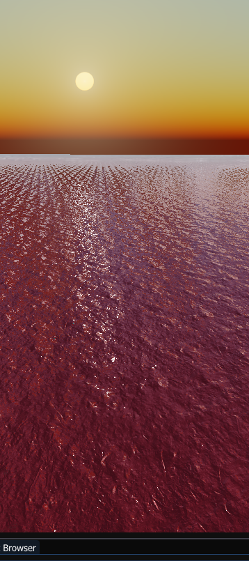
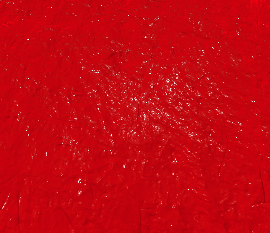
So what about with roughness added, this is where it could all fall apart without the energy conservation part of the equation:

Looks pretty good to my eyes.

So what I essentially now got it this:

specular = D * G * 0.04f;

ambient = pow(lerp(ambientFinalColour, lightColour, saturate(NdotL)) * (1 + F), 2.2);

indirectDiffuse = (irradianceColour * Albedo * Ambient * fullyLit * (1 + F)) + (irradianceColour * Albedo * shadowColour * (1 - fullyLit));

So I've added the Fresnel term into the ambient and indirect diffuse colours. I'm ignoring the fact that I've essentially multiplied in the straight on Fresnel term (0.04) and then also added it to the diffuse because the difference is negligible. The good thing about this is that it's going to be faster as you don't have those extra calcs in the denominator.

I can also add in a light intensity variable too, just to increase the size of the specular highlight without causing any issues (seen here with IBL on):

Be interested to hear what you think and if you can try this in your engines to see if you get comparable results.

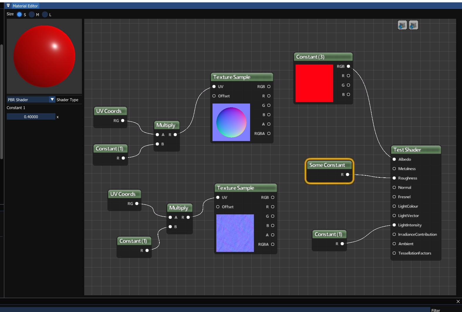
I'll be sharing a video on my material editor soon too, just to showcase it (excuse the shameful copy of a certain well-known editor's textures…, I'll change these at some point):

Edit: I realise I haven't got my environment map for IBL sync'd up with the atmosphere - I was just trying out a new cheap scattering technique I found on ShaderToy ?

Advertisement

Personally I'd rather rely upon decades of research in BRDFs and shading than what “looks pretty good”. The existing PBR BRDFs have been developed to closely match the behavior of real-world materials (e.g. by matching rendered images to real photos with various light/view/normal vectors). For a microfacet BRDF, it is indeed correct to use the half vector instead of the reflection vector, Unreal is doing the right thing.

RobM said:
So what I essentially now got it this:
specular = D * G * 0.04f;
ambient = pow(lerp(ambientFinalColour, lightColour, saturate(NdotL)) * (1 + F), 2.2);
indirectDiffuse = (irradianceColour * Albedo * Ambient * fullyLit * (1 + F)) + (irradianceColour * Albedo * shadowColour * (1 - fullyLit));

This doesn't make much sense to me. Why is ambient raised to 2.2 power? If you're trying to convert from sRGB to linear RGB, it should be done before any lighting calculations. Why are you interpolating between diffuse and ambient light using the fullyLit variable? Ambient light should always be present, with diffuse and specular added on top.

You're fully free to use such hacky shading, but I imagine it would break in certain situations while a proper BRDF would work in all lighting situations. For comparison, here is my shader code for the Cook-Torrance BRDF, which I'm 99% sure is correct.

float geometrySchlickGGX( float nDotV, float roughnessK )
{
    // k is a remapping of the surface roughness, where:
    // k = 0.5 * (roughness)^2
    float numerator = nDotV;
    float denominator = nDotV * (1.0 - roughnessK) + roughnessK;
    return numerator / denominator;
}
float geometrySmith( float dotNV, float dotNL, float roughnessK )
{
    float ggx1 = geometrySchlickGGX( dotNV, roughnessK );
    float ggx2 = geometrySchlickGGX( dotNL, roughnessK );
    return ggx1 * ggx2;
}

void evaluateBRDFCookTorrance( in vec3 lightColor, in vec3 L, in float visibility, in float attenuation, in float ambient )
{
    #if DIFFUSE_LIGHTING || SPECULAR_LIGHTING || AMBIENT_LIGHTING
        float cosL = dot( surfaceNormal, L );
        float dotNL = max( cosL, 0.000001 );
    #endif
    
    #if AMBIENT_LIGHTING
        ambientAccumulator += lightColor*(ambient * ambientShade(cosL) * attenuation);
    #endif
    
    #if DIFFUSE_LIGHTING
        // Diffuse Fresnel Term
        float invDotNL = 1.0 - dotNL;
        float invDotNL2 = invDotNL * invDotNL;
        vec3 Fdiff = F0 + (1.0 - F0) * (invDotNL2*invDotNL2*invDotNL);
        
        diffuseAccumulator += lightColor*(1.0 - Fdiff)*(dotNL*visibility*attenuation);
    #endif
    
    #if SPECULAR_LIGHTING
        // Compute half vector (L + V)
        vec3 H = normalize( L - surfaceDirection );
        
        // Compute dot products.
        float safeDotNV = max( dotNV, 0.000001 );
        float dotNH = max( dot( surfaceNormal, H ), 0.000001 );
        float dotHV = max( -dot( H, surfaceDirection ), 0.000001 );
        
        // Geometry term G.
        float roughness2 = surfaceRoughness * surfaceRoughness;
        float G = geometrySmith( safeDotNV, dotNL, roughness2*0.5 );
        
        // Normal distribution function D. (Beckmann distribution)
        float dotNH2 = dotNH * dotNH;
        float dotNHR2 = dotNH2 * roughness2;
        float D = exp((dotNH2 - 1.0)/dotNHR2) / (dotNH2*dotNHR2);
        
        // Specular Fresnel Term (Schlick approximation).
        // H dot V is correct for microfacet BRDF, even though Schlick specifies N dot V.
        float invDotHV = 1.0 - dotHV;
        float invDotHV2 = invDotHV * invDotHV;
        vec3 Fspec = F0 + (1.0 - F0) * (invDotHV2*invDotHV2*invDotHV);
        
        // Cook-Torrance Specular BRDF (without Fresnel Fspec, multiplied below)
        float specularBRDF = (D * G) / (4.0 * safeDotNV * dotNL);
        
        specularAccumulator += (lightColor*Fspec) * (dotNL*specularBRDF*visibility*attenuation);
    #endif
}

And here is an image I generated using the above code to show the behavior of the specular highlights. You can see I have elongated specular highlights on the ground, and the highlight on the sphere is crescent shaped at grazing angles.

Hacky…? If you want to rely on decades of research in BRDFs, that's your choice (and is what I have also done), but if you're going to say what you've done is 99% correct, at least come back with a decent example.

Two out of the three specular highlights you've posted (on the right side of your sphere and the ground) look completely unnatural. A circular light (e.g. the sun), when reflected in a perfectly shiny surface will be circular, not elliptical like yours is. This is the case in real life, no matter what the glancing angle is. The lobe on the right side of the sphere is also weirdly cut off. Just looks wrong.

Get a torch and a mirror (or shiny flat object) and try it for yourself. I would imagine if you added some texture to your flat red plane, the long trail would also look wrong. The tried and tested BRDFs may be tried and tested, but that doesn't mean they look right compared to real life…

Edit: that pow shouldn't have been there, that was slightly older code, but thanks for pointing it out (at least)

RobM said:
A circular light (e.g. the sun), when reflected in a perfectly shiny surface will be circular, not elliptical like yours is.

First of all, the surface I rendered was not perfectly shiny, it had a roughness of around 0.2. The roughness causes the specular highlight to elongate into an ellipse as the various microfacets reflect the light. With microfacets the surface does not behave as a perfect mirror, which seems to be what you are expecting.

RobM said:
The lobe on the right side of the sphere is also weirdly cut off.

This is due to the shadow masking function and/or the shadow map. You shouldn't get a specular highlight where the light cannot possibly reach.

Second, I pointed out at least two mathematical errors in your shader code which will cause it to produce inaccurate results.

Third, here are some more images showing the behavior at different roughness. You can see that the highlight becomes more circular as the roughness is reduced. Note that I clamp the minimum roughness to 0.05 to avoid numerical issues. The light is the black square.

0.05 roughness
0.15 roughness
0.25 roughness
0.45 roughness
0.1 roughness with water normal + height map

Here is a real picture of water to illustrate the correct behavior.

You can see that the reflection of the light source (the sun) has been broken up and significantly elongated due to the waves. The same thing occurs with a microfacet BRDF but at a much smaller scale (where the waves are the microfacets). The bumpiness causes different parts of the surface to reflect the light to the viewer. The reflection of the light source is not circular at all.

If we were to view the reflection such that the light vector is the same as the view vector (i.e. both are parallel with surface normal), then the specular highlight would appear fuzzy and circular. The viewing angle definitely matters. Perpendicular to the surface, highlights are circular, but at grazing angles they become elliptical.

I agree that the specular reflection on your flat plane looks right, the elliptical-ness as it becomes rougher does look more natural (and you get this with the half vector, which I've removed for now), but I still feel like the lobe on the sphere looks wrong. It's this effect that I'm really trying to change so it looks right (to me).

Aressera said:
Here is a real picture of water to illustrate the correct behavior.

Yes, I've spent a fair amount of time studying why we see the stretched specular reflections on a sunset over water and I understand the reasons why it happens. I just hadn't considered that the microfacet calcs (with half vector) were achieving that that at the roughness level. In my mind, I left that to the normals but I guess it's important for realism.

This topic is closed to new replies.

Advertisement