As for the exporting of the model, the DirectX export script that comes with Blender doesn't work so well for me. What you need to do is download this one and drop it into the Scripts folder of your Blender installation. It will overwrite the one that came with Blender. If you don't want to overwrite the old one, simply change the extension of the old one from .py to .old so that it will still be there if you want to change back to it.
Now for a short refresher on conventions I use and some Blender hot key notes:
Feel free to skip this if you are comfortable with Blender hot keys or you just did Part I; this is straight from there.
I will use some abbreviations during this tutorial, defined as the following:
- LMB = Left mouse button
- MMB = Middle mouse button
- RMB = Right mouse button Most hotkeys involve a single button, or a button in combination with Shift, Alt, or Ctrl. I will use the following conventions when using hotkeys:
(letter to press KEY)
Examples:- (EKEY) Press the "E" button on your keyboard. This is your extrude command.
- (GKEY) Press the "G" button on your keyboard. This grabs the current selection and lets you move it.
- (Shift+MMB) Press and hold the Shift key and the middle mouse button. This will pan the current view. I will also on occasion use red circles in the pictures to show which vertices I am referring to.
A few things to keep in mind:- To select an object or vertex in Blender, use the right mouse button (RMB).
- When performing some actions, like Scale (SKEY), Move (GKEY), or Extrude (EKEY), you can cancel the action by right-clicking (RMB). Left-clicking (LMB) accepts the changes.
- To select multiple objects or vertices hold down SHIFT and make your selections with the RMB.
- The SHIFT button will also deselect any selected objects or vertices when used with the RMB.
- To toggle in and out of edit mode for the selected object, use TAB.
- The SPACEBAR is your friend. That is where you find many useful commands and tools, including primitive objects. The 3D Cursor, which looks like a red and white crosshair, is where the new objects will be placed. When you start Blender this will be in the center of your view. You can change it's location by left clicking (LMB) anywhere in the view. Keep in mind that it's 3D space, so to get correct placement you may have to adjust it in several views; Front, Side, and/or Top.
- Use (AKEY) to select/deselect all objects. If one or more objects are already selected, but not all of them, (AKEY) will deselect all. Hitting it again will select everything.
- Any window that contains the curser is the selected view. Simply move the mouse to a different window to make it the current view.
- You can switch your model's appearance from Wireframe to Shaded by using the ZKEY as a toggle switch. There is also the option to show textures and/or materials by using SHIFT+ZKEY as another toggle.
- Change the view in a window using the NUMPAD keys, 1 for front, 3 for side, and 7 for top. Holding the Alt key with 1, 3, or 7 will give you the opposite view of those buttons.
- Rotate a view using the NUMPAD keys 2, 4, 6, or 8. You can also rotate freely by holding the MMB and dragging the mouse.
- By scrolling the MMB up or down you can zoom in or out of the current view.
- You should save often by using (CTR+WKEY), which is Save, or by using (F2), which is Save As. I'm not going to tell you how often to save, that's a personal preference.
- You can clear up your view while in Edit Mode (Toggle on and off with TAB) by selecting vertices you're not using and Hiding (HKEY) them. Hidden vertices will remain hidden if you leave Edit Mode and then re-enter it. To Unhide them, use ALT+HKEY. If you haven't done so already, fire up Blender and load up your final sword file from Part I. You can use (CTRL+O) to open the last file you used.
In our Side View, go to the Current Window Type button, it's the one that looks like a crosshair, and choose the UV/Image Editor Window:
Now over in our Front View, let's enter Face Select Mode (FKEY). If you give it a good Rotate you can see how it appears that some of the faces are invisible. Actually, they are there, they just need their Normals flipped.
While we are still in Face Select Mode, enter Edit Mode (TAB) as well. Your faces should all turn Purple.
Select All (AKEY) and to flip our normals use (CTRL+NKEY). It will ask if you want the Normals to face out; yes you do.
Exit Edit Mode (TAB) and your faces should now all be white. On more complex models this trick will not work on every face. The faces that still appear invisible should be selected individually in Face Select Mode (FKEY), then enter Edit Mode (TAB) and try flipping the normals both inside (CTRL+ALT+NKEY) and outside (CTRL+NKEY) to see which way gives you the correct results.
Give it another good Rotate to make sure all of the faces are white. They are, good.
Now switch the view back to Front (NUMPAD 1) and choose our UV layout by selecting LSCM in our Specials Menu (UKEY):
In our UV window we see how it calculated our UV map. Looks like crap. Let's fix it by marking Seams along our model. Seams will tell the UV unwrapper where to cut the model.
Back to Front View. Exit Face Select Mode (FKEY), enter Edit Mode (TAB), use your Select tools (BKEY) and drag to select the ends of the crosspiece and zoom in (MMB) to select all points under the blade:
To clear up our view we will Hide (HKEY) all of these vertices. Rotate (MMB) the view a little and select (SHIFT+BKEY)the six vertices around the base of the blade and hide them (HKEY)as well:
Now Select the four vertices that make up the base of the blade and mark them with a Seam (CTRL+EKEY).
Still at the base of the blade, Deselect (SHIFT+AKEY) the two vertices that make up the flat of the blade, but be sure to keep the two edge vertices selected. At the top of the blade, also Select (SHIFT+AKEY) the three vertices that make up the tip and the top of the edges. Mark a seam (CTRL+EKEY).
Now let's check our progress. Exit Edit Mode (TAB), enter Face Select Mode (FKEY), and select LSCM in our Specials Menu (UKEY):
A little better on the blade, let's fix the handle.
We need to swap the visible blade with the invisible handle.
Front View (NUMPAD 1), Deselect all (AKEY), you may have to hit it twice, and Unhide the handle (ALT+HKEY).
We will now forego the keyboard and *GASP* use the on screen buttons for a second. The bottom of the screen has a bunch of buttons. We need to switch them to the Edit Buttons. It looks like a square with 4 yellow vertices:
Now on the new button set, toward the right of the screen you will see one that says Select Swap. Push it.
I don't know of a hot key to do that, but now your model's vertices should have switched which ones were selected. Hide (HKEY) the now selected blade and you should only see a handle:
(NUMPAD 3) into Side View and Select (BKEY) the middle vertices by dragging a box around them. You can see a thin grey line when you do this:
Mark a Seam (CTRL+EKEY) along this selection.
If you want to check our progress now, exit Edit Mode (TAB), enter Face Mode (FKEY), and LSCM in the Specials Menu (UKEY):
A few more seams will do it.
Back to Front View (NUMPAD 1), Edit Mode (TAB), Deselect All (AKEY Twice), and drag a box to Select (BKEY) the row just under the crosspiece and mark a seam (CTRL+EKEY).
By now you know the buttons to check the new map, if you want.
We need another seam to connect the previous seam with the seam at the base of the blade. Mark a seam on both sides using these four vertices:
Deselect All (AKEY Twice) and Select (SHIFT+AKEY) the 12 vertices that make up the top of the crosspiece. Mark a seam.
To see where you've put seams, exit Edit Mode (TAB) and enter Face Select Mode (FKEY.) Deselect All (AKEY) and you will see bold black lines at all of our seams:
Select all (AKEY) and unwrap again. LSCM under the UKEY menu. You get this:
The vertices in the UV Window can be pushed, pulled, scaled, or moved just like when in Edit Mode. Move them around and scale them to fill the window a little better. Then Pin them all with(PKEY). Pinning comes in handy with more complex models. When unwrapping a fancy model, you could pin a few vertices and unwrap again. It forces the LSCM to base it's calculations around the pinned verts. You would repeat the pinning several times to get it right, but you have to recalculate the LSCM every time to do any good. Our model wasn't too bad so we pinned it at the end. You can also unpin them by using (ALT+PKEY) if you need to.
To make a texture map we need to export our layout. Right under the UV window is a UV menu button. Click it and then select the option Save UV Face Layout...
That in turn brings up some more buttons in the bottom window. Things to change here are the Size field, which is how many pixels square you want the texture to be and the export path you want the map to be in. You could also change the wire size if you want.
Open up the exported map in your drawing program of choice. I used another free program, the Gimp. Paint over your map and save it. I'm not going to show how to do that, there are tons of tuts out there on how to use the different drawing programs and I don't know which one you would use anyway. If you don't like working with .tga files or your program of choice doesn't support them, just grab the Gimp save it under a different format. Blender can open the map up in other formats, such as .bmp or .jpeg.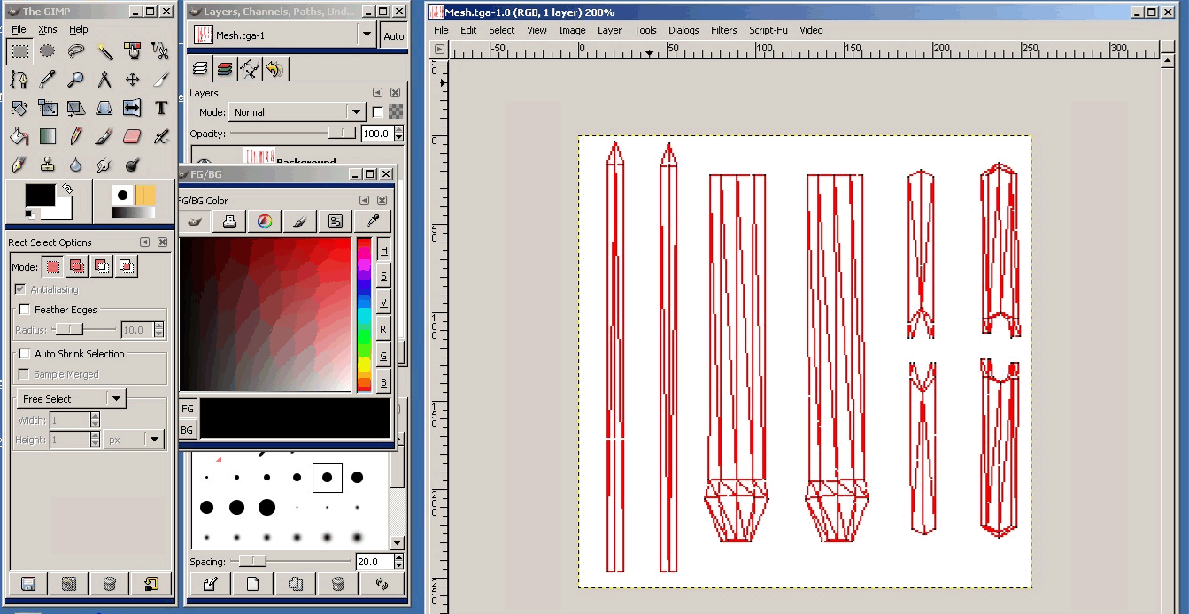
Go back to Blender. Under the UV window, open the Image menu which should have only one option, Open. Find the texture map you painted and open it.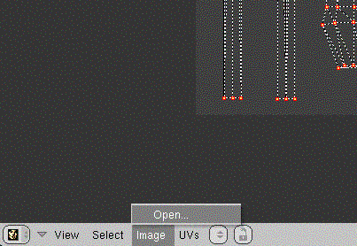
It should line up perfect. Make sure you're not in Edit Mode. To see it on the sword, you can change the Viewpoint Shading to Textured by using (ALT+Z).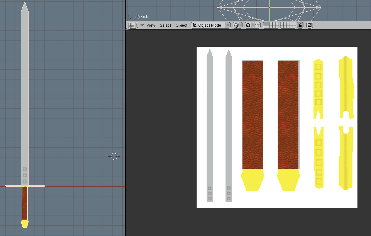
Now the easy part. To export it to DirectX, go up to File, Export, DirectX and choose a location and name. Easy, huh?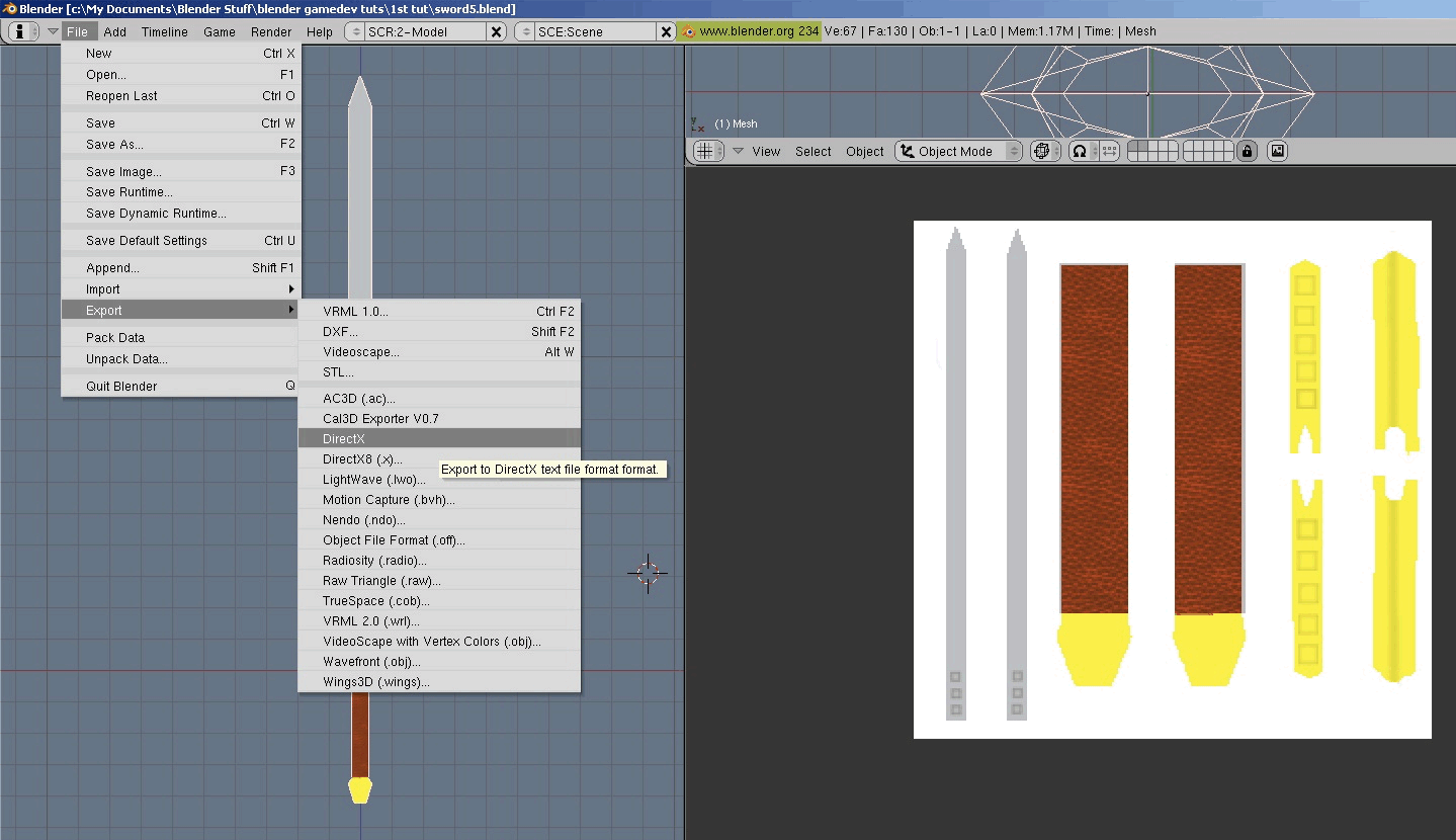
I know it's bad to assume, but assuming you have the DirectX 9 SDK installed, open up the Mesh View under DirectX Utilities and open up the exported file. Make sure the texture and model are in the same folder. Ahhh...it works! This needs to be in a game somewhere.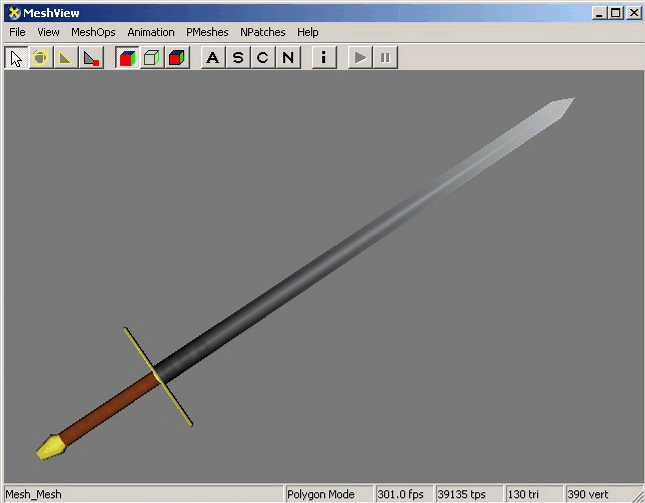
That ends our journey to make and texture a game model with Blender. If your sword didn't come out quite the way you wanted, you can grab my .blend file and the texture I made here. Feel free to send me any feedback, questions you may have, or even to show me a final textured picture of your game models [email="yoda@yodasworld.net"]here.[/email] That would be cool.
--Yoda


