Water plays an important role in all terrain renderers used in modern games and visualizations to present outdoor areas. This is because it improves general image quality in an extent bigger than any other technique and makes it more photorealistic. Alas, even though it tends to look better and better with every game released it is still far from being realistic. Besides, deferred shading gains popularity every month. Many newer games and engines make use of it, eg. Starcraft 2 and Tabula Rasa. Though deferred shading is typically used to limit lighting-related operations from O(objects_number * lights_number) to O(objects_number) I will prove that it can be helpful in many more algorithms.
In this article I will describe a technique of realistic and flexible water rendering by using bump mapping in the post-process stage just after deferred shading. The presented technique fits into the concept of deferred shading pretty nicely, i.e. it helps to avoid additional geometry rendering. A description on deferred shading can be found in [[alink=ref]1[/alink]], [[alink=ref]2[/alink]] and [[alink=ref]3[/alink]]. It is possible to implement this technique using forward rendering but in this case it seems less natural and may require additional work.
The presented algorithm eliminates the majority of the flaws of typical techniques used for water rendering such as hard edges or unrealistic colour extinction. I will talk shortly about common drawbacks in the section "Traditional approaches to water rendering".
Theory behind water
The theory behind water is very complex and not fully understood. It will suffice to say that there is no adequate formal model describing it so far. Survey conducted by Guillot [[alink=ref]4[/alink]] proved that none of the 46 models he analyzed is valid when compared to reality. Existing models are also a way too complex and computationally expensive to be used for real time applications, especially games. A game should not spend most of its CPU or GPU processing time just to update and render realistic water.
So a completely different solution has to be found.
In my opinion the theory of water for real time applications can be divided into two categories:
- Waves - their animation, propagation and interaction with the rest of the world
- Optics.
To simulate waves propagation, FFT (Fast Fourier Transform [[alink=ref]5[/alink]]) is frequently used. In this article I do not focus on waves propagation and so I will skip the theory behind it. I strongly believe that what is more important for good looking water is optics and I will describe it in a very detailed way.
Reflection and refraction
A light ray going through the water surface gets reflected and refracted, causing specular, caustics and light shafts to appear. Light shafts and caustics play an important role in underwater scenes, however for an observer standing above the water surface they do not improve the quality of water that much. A key to describing reflection and refraction is the Fresnel term. The Fresnel equation tells us how much light is reflected and refracted when it crosses a border between different media (in this case water and air). We have to make an assumption that light goes through two materials only as the term shown later does not apply in a more general case. Besides, both of them have to be homogeneous and one of them has to have a higher density. "Air - water" pair falls well into this assumption. However "air - window glass" does not as it consists of three materials (air - glass - air). Graphically it is depicted as follows:
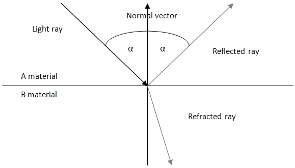 Light ray reflection and refraction
For any given angle of light a and refraction coefficients describing both materials A and B, namely
n[sub]A[/sub] and
n[sub]B[/sub], we use following notation:
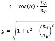
The Fresnel term could then be defined as follows:
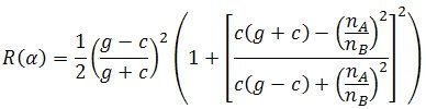
However this equation is too complex to be computed on GPU per-pixel. Therefore, a frequently used approximation is given below:

This function is very similar to the one described previously so the loss of quality is really insignificant.
R(0) is constant and therefore it should be computed only once and then passed to the pixel shader.
Index of refraction

for water is equal:
IOR = 1,33333
Colour extinction
One of the most important aspects of proper water rendering are colour extinction as light goes deeper and deeper and also light scattering. However, rarely does anyone pay attention to that, although these are the two phenomena which cause water to have the colour we see. This colour is called the "apparent one" and can be totally different from so-called true water colour. To find this true colour, one has to filter out all the particles and organic material from water. It is done in laboratories and for us is not usable. One thing to note is that true water colour is bluish (not completely transparent as it was believed some time ago). We will use this information later on. For each component of the light spectrum, speed of extinction is different. This is due to different wavelengths of the components. The visible range of light is exceptional in that attenuation fades slowly compared to infra-red or ultraviolet. For them, absorption rate is so high they fade away entirely at a maximum depth of a few centimetres. In the table underneath, average depths at which light components die out are presented. The table is valid only for very clean waters. In the case of muddy ones like lakes or rivers it has to be modified:
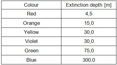
We make an assumption that extinction is linear with depth. In general this is not true as water is not homogeneous at its whole depth. Many waters consist of tiers of different temperatures and density which makes them different mediums. However, to simulate water in a convincing way it is not necessary to take this into account.
Besides, extinction speed ratio and water colour are also influenced by chemical composition of the water area bottom, level of siltation, existence of organic materials (like algae or plankton) and even sky colour!
An important conclusion from this deliberation is that the further from the equator the water is the more green its colour becomes.
Traditional approaches to water rendering
The traditional approach to the water rendering problem [[alink=ref]6[/alink]] is based on rendering a plane with reflection and refraction textures applied to it in the level determined by the result of the Fresnel formula. To give water surface the impression of being wavy, the projection texture coordinates are modified (displaced) along a normal vector at a given water point. This normal vector is usually obtained from a normal map. This technique can be used only for lakes, however, as these waves are way too low to represent ocean ones. An alternative to this technique is the use of dense vertices grid (the technique known as the projected grid). Vertices in this technique are transformed in the vertex shader and this way it is possible to achieve realistic waves (not an imitation as in the previous example). In the pixel shader, reflection and refraction textures are applied as previously.
A modification of this technique in turn is to use the vertex texture's fetch mechanism [[alink=ref]7[/alink]], allowing sampling of the texture in the vertex shader. Thanks to that at this stage it is possible to use a height-map. This mechanism, introduced in the 3.0 shader model, gives much better results but still they are far from being realistic and are not yet used that often for water rendering.
As you can see, the majority of existing and popular techniques focus primarily on modelling the appearance of the surface and less on the optics. I hope you remember me claiming that optics are very important.
Although these approaches are the most popular techniques for rendering water up to now (despite the ever-increasing power and the capabilities of GPUs) there are several
problems associated with them:
- The transition between the shore and the water is very hard and thus unrealistic. The resulting water often resembles metallic substances like mercury. In nature, water is free from sharp edges - they are always very soft and smooth. Even liquids with a very high density (like oils) do not have them.
- To obtain good quality waves it is required to have an adequately dense mesh, otherwise the waves will have sharp edges.
- It is difficult to obtain the correct colour extinction with depth, as well as the effect of the transition from the shallow water to the depths. This is due to the fact that usually in the process of rendering water we have no information about the depth of water at a specific point of the scene. Thus, the water is simplified, and has incorrect colour. Some implementations make use of a so-called depth map for that - a static texture describing the depth of the water area. However, even the appearance of very large objects on the bottom (for instance a ship wreck) will not change water colour whereas it should.
- The solutions are rather inflexible - a share of them can be used only for rendering oceans, some for lakes.
- It is recommended that some form of LOD techniques will be used in order not to process too much information about distant parts of the water from the observer.
- Rendering multiple different areas within a single scene is often difficult.
Presented approach
The presented approach is based on the simple fact that water is drawn in the phase of image post-processing and is not associated with any geometry. In addition, I make an assumption of the use of deferred shading since implementation in this case is simpler and seems to be more natural. Thanks to these assumptions at this stage we have the geometry buffer filled with data. In particular, we have easy access to information about the position of each vertex visible from the camera position point of the scene. Since the geometry of the buffer is nothing more than the geometry stored in the image space, modifying it to impact the actual geometry of the scene is possible. This simple fact allows us to completely change the approach to rendering displacements and bumps. It becomes possible to move many algorithms from the geometry stage to the post-processing stage. However, I will only show how to make water this way. At the same time, we can easily get rid of the disadvantages of the traditional techniques of rendering water, which were mentioned in the previous section. The presented approach does not, however, focus on the animation of waves propagation in the water. The decision to use static height-maps, as in the example, or dynamic ones modified in accordance to the FFT, is up to you.
Modifying existing geometry
Notice that if you make modifications to the texture storing the scene point positions it becomes possible to achieve a water surface with convincing waves. We can think of this position-storing texture as of depth of water at any given point. If you know the position of the water surface
L and the position
P of the scene pixel, then
depth =
L -
P.
Depth = 0 corresponds to the water surface and
depths < 0 correspond to the points located above the surface and so they can be skipped as they do not require further processing.
In order to obtain waves, a traditional height-map in greyscale is used to alter this depth.
The algorithm to create waves is relatively simple. It relies on tracing the ray from the position
P of the scene to the observer and extruding waves in this direction. Several iterations are done. In each of them we sample our height-map and bias the water surface level by this value.
- For each scene point P:
- Current level of water surface L = level of water surface.
- If P.y > L + H (maximum wave height), then end, because point P is above the water surface.
- Calculate the eye vector E as a difference between the pixel P and the observer position: E = P - Observer Position.
- Normalize E: E = Normalize (E)
- For the current level of water surface L, find a point of intersection with the vector E. Mark it as the position of water point S. In other words, find the point of intersection of the plane W = (0, 1, 0,-L) with the vector E.
- Perform n iterations
- Sample the height-map at the point defined by S and in the direction of the vector E. The result is bias B.
- Multiply B by the maximum wave height H: B = B * H
- Set new L as: L = L + B
- Find new S on the basis of new L value
- Calculate the amount of accumulated water along the ray as A = length (P - S)
- Calculate the depth of water at this point as D = S.y - P.y
Note that the results, especially the amount of accumulated water
A and depth
D will be used later to simulate several aspects of water optics.
The computation of normal vectors
To have realistic and convincing water it is essential to compute normal vectors. While in the case of a vertices grid, normal vectors are known already at the stage of processing geometry in the vertex shader, in the case of the presented technique, they must be calculated entirely in the pixel shader as there is no real geometry. Luckily, a simplified way of computing normal vectors known from terrain rendering applies here as well. In order to calculate normal vectors, the height-map has to be sampled in four adjacent points to the processed one, that is:
N = {
W -
E, 2
d,
S -
N}
W,
E,
S and
N are sampled directly from our height-map.
Although these normal vectors could serve as the ones used in the lighting and shading calculations, much better results can be achieved using an additional normal map. This is due to the fact that normal vectors so far are way too smooth whereas to achieve good water quality it is extremely important that detail will be present. It can be obtained only by using normal vectors with much higher resolution.
To do this we are going to use the traditional normal mapping technique. Since there is no geometry, we do not have information not only about the normal vectors (which are already set) but also about the tangent and binormal ones which are necessary for the validity of the calculations. There is an approximate method of their computation in the pixel shader, fully described by Schuler [[alink=ref]8[/alink]]. Thanks to that, the construction of the matrix necessary to carry out normal mapping is possible and pretty easy. The code is as follows:
float3x3 compute_tangent_frame(float3 Normal, float3 View, float2 UV)
{
	float3 dp1 = ddx(View);
	float3 dp2 = ddy(View);
	float2 duv1 = ddx(UV);
	float2 duv2 = ddy(UV);

	float3x3 M = float3x3(dp1, dp2, cross(dp1, dp2));
	float2x3 inverseM = float2x3(cross(M[1], M[2]), cross(M[2], M[0]));
	float3 Tangent = mul(float2(duv1.x, duv2.x), inverseM);
	float3 Binormal = mul(float2(duv1.y, duv2.y), inverseM);

	return float3x3(normalize(Tangent), normalize(Binormal), Normal);
}
where:
- Normal - normal vector, in our case, the vector set a moment ago.
- Position - position in the world space,
- UV - texture coordinates.
Having this matrix we can now sample our normal map texture in a traditional way. The overhead is only a dozen or so arithmetic instructions associated with matrix construction above but believe me the result is worth its cost:
float3x3 tangentFrame = compute_tangent_frame(normal, eyeVecNorm, texCoord);
float3 normal = normalize(mul(2.0f * tex2D(normalMap, texCoord) - 1.0f, tangentFrame));
Just be aware that the normal vectors have to change over time. If not, the water will resemble a rigid material like plastic. Therefore, the normal map has to be sampled several times with texture coordinates varying over time. This way it is possible to achieve interfering waves of different sizes that really looks fantastic.
Optics
As already mentioned several times in this article, optics play a key role in the convincing appearance of water. In this section we are going to focus on its individual aspects.
Reflection and refraction of light
The proposed technique does not support any new way of rendering the reflections. Thus, it should be done the traditional way. This means that the whole scene must be rendered to the texture with an altered view matrix (or world one). Picture below presents the concept:
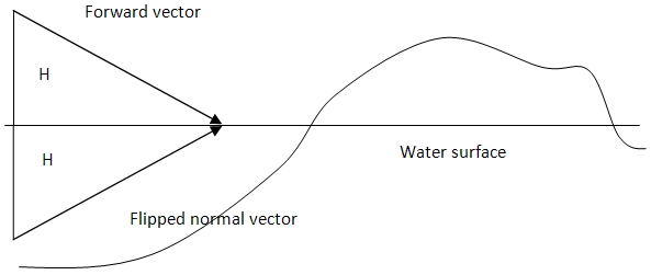 The idea of rendering the scene to the reflection texture
The location of the observer is reflected with respect to the water surface. The forward vector is flipped as well as the up vector has to be recomputed to match the others.
Water surface is also set as the user clipping plane to avoid rendering geometry above it as it would cause the reflection texture to contain too much data and therefore being invalid. For DirectX 10 and newer, SV_ClipDistance semantic should be used instead. Performing this step at the pixel shader level is not the very best idea as it is just too late - the pixel shader would be run for every pixel and thus more operations would have to be performed than is really necessary. Even if a pixel will be discarded at the very beginning of the pixel shader.
In contrast, in the case of refraction we can make some simplifications, which for most users will remain negligible. Many of the post-process effects use information about the current state of the frame buffer as they modify or operate on it. In the case of water which is treated in the paper as such we can also benefit from this. This way you will not be rendering the scene to the next texture, but even so the final result will remain satisfactory. This solution also better fits the idea of deferred shading i.e. not rendering the same geometry many times. So what has to be done is to put frame buffer content on the screen and modify it slightly to create the impression of movement with the waves. In my implementation I have just changed screen space quad texture coordinates using time and the sine function.
Specular
Another important factor affecting the quality of the water effect is specular highlighting, in some implementations also called glare or sun glow. Water is characterized by high shininess. In this article we take into account only specular caused by global light - sunlight. Local lights influence water in lesser extent and therefore they can be skipped without sacrificing too much quality. The calculation of sun glare may be done in a number of ways. In my opinion, the best results can be achieved using this snippet I found some time ago:
half3 mirrorEye = (2.0 * dot(eyeVecNorm, normal) * normal - eyeVecNorm);
half dotSpec = saturate(dot(mirrorEye.xyz, -lightDir) * 0.5 + 0.5);
specular = (1.0 - fresnel) * saturate(-lightDir.y) * ((pow(dotSpec, 512.0)) * (shininess * 1.8 + 0.2));
specular += specular * 25 * saturate(shininess - 0.05);
The key here is the first line of code, which reflects the eye vector so that the incidence angle is equal to the emergent angle. Therefore, an angle between normal and normalized eye vector is found. In the next few lines there is only a slightly modified process of specular calculation. The constants' values can be changed but after testing several ones I think these gives the best results. For the shininess parameter I suggest values in the range 0.5 to 0.7.
Colour extinction
In many implementations of the water effect, light extinction is ignored. If it is implemented it is often simplified to multiplying water colour by some bluish shade. However, as I wrote in the section "Theory behind water" it is one of the most important factors affecting the apparent colour of the water. In the proposed solution light extinction is divided into two phenomena:
- Colour extinction with a depth that makes all objects have bluish colour from a certain depth onwards
- Colour extinction with increasing distance from the observer, the so-called horizontal transparency of water.
Depending on the depth at the given point and the distance from the observer, water will have a different colour. We first define the vector of colour extinction, which is responsible for the rate of extinction of the r, g, b components of light. On the basis of the table from the theory section this vector can look this way:
extinction = [4.5;75.0;300.0]
Then the first attempt to compute proper water colour can be as follows:
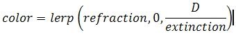
where:
- refraction - colour of refracted scene,
- D - the depth value determined at the end of "Modifying existing geometry" section
Unfortunately this formula has a few flaws:
- The colour fades away only with depth, however there is no decay along the eye vector. This makes water pixels far from the observer have the same colour as ones near it, whereas they should be much darker.
- Moreover, control over water colour is limited and very difficult. While the clean waters are relatively easy to obtain, muddy waters like lakes are much harder. It is because in the above formula, water colour is not used explicitly.
- The above calculation does not take into account the true colour of water, which is bluish. In this model it is white.
We have to therefore modify our computations:
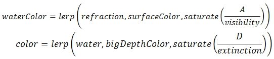
We introduced several new quantities to our formula:
- The surface water colour (surfaceColor), which can be treated as a true colour of the water
- The colour of deep water (depthColor)
- Amount of accumulated water A as mentioned in the section "Modifying existing geometry"
- Introduction of the horizontal visibility (visibility). The smaller the value of this parameter, the less transparent water will be.
In the particular case for
surfaceColor = 1 and
depthColor = 0 final colour of the water will be very similar to that from the previous solution. What we get is the final refraction colour. Then using the value from Fresnel term we blend reflection with refraction and add specular to the result. This way, however, water will have hard shores and that was what we strove to avoid. Therefore, we once more blend the result with refraction to an extent determined by the input parameter specifying
shore hardness (1 by default) multiplied by parameter A (water accumulation). By using the shore hardness parameter we will still be able to obtain the hard edges (sometimes they can still be useful, especially when rendering NPR - non-photorealistic rendering).
Possible improvements
One of these add-ons that you can get with a small amount of work and yet which significantly improves the realism of the water effect is foam. It arises when the water hits the shore and at the tops of more choppy waves. The first of them, i.e. coastal foam, can be obtained by making an assumption that foam begins at the edge (that is, at the depth equal to 0), and to a certain depth
H[sub]1[/sub] remains constant, and in the range extincts completely.
Whereas the latter can be achieved by using the following formula:
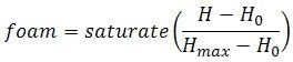
where:
- H - current height,
- H[sub]0[/sub] - height at which foam appears
- H[sub]max[/sub] - height at which foam dies out.
This gives you information how much foam is visible. However, to really get it on the screen you have to sample some foam texture and multiply its colour you get by the value found above. Using a photo of coastal foam works good for that. Another possible extension is to add the interaction between world objects and water. The basic form of interaction will be provided if you use foam as described above. Since it is closely related to the depth at the point of the water area, it will appear wherever the depth is small. As a result it will appear whenever an object falls into the water.
However, the possibilities of interaction between water and the rest of the scene are literally unlimited. By modifying height-map either on CPU or in pixel shader you can easily introduce local disturbance for instance.
 Even though I consider foam as an "improvement" it greatly improves general image quality and makes it warmer. Therefore you should regard using it as often as possible.
Disadvantages of the presented technique
Although the presented technique removes most of the defects of existing water rendering techniques listed in the section "Traditional approaches to water rendering" there is still enough room for improvements due to several drawbacks of the current algorithm:
- It increases fill-rate as it is done in post-process and at the same time based on deferred shading. Fortunately, in most cases the water should not occupy more than half of the screen. On the other hand, often there is no need for LOD, since most of the screen pixels will be near the observer.
- Water looks not that good at oblique angles. In order to get rid of this problem, it is possible to apply a different bump mapping technique. The alternative is to move the normal vector towards the observer for distant waves, which will improve their quality, as their back faces will be invisible.
- In the presented approach local lights do not affect the colour of water. You can try to move water rendering before the lighting phase (we can then modify the normal data). This, however, will require modification to the existing rendering chain.
Final results and summary
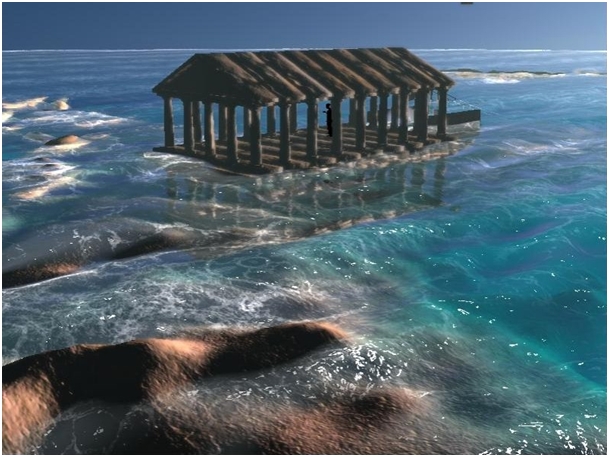
 You can achieve many different kinds of water using the presented technique, from tropical warm seas to cold lakes.
The algorithm presented in this paper is a good alternative to the popular techniques used for rendering water effects. By using calculations based on the observation of the phenomenon, rather than on existing mathematical models, I have managed to achieve a realistic effect, which in the case of properly selected parameters' values makes it possible to achieve results comparable with much more expensive models. It is also a flexible solution - the appearance of water can be controlled through a number of attributes. This makes it suitable for a wide range of effects no matter it be lakes or oceans. You can even have several areas of radically different waters at the very same time.
Besides, as it does not rely on geometry it eliminates the most common flaws of the popular techniques discussed in more detail in the section "Traditional approaches to water rendering" of this article.
A word on implementation
The
provided shader has been implemented using HLSL and DirectX 9. At present it requires a SM 3.0 capable GPU to run, however, it can be heavily optimized as my main concern was to make it as readable and simple as possible. Several textures are used in the code:
- heightMap - height-map used for waves generation as described in the section "Modifying existing geometry"
- backBufferMap - current contents of the back buffer
- positionMap - texture storing scene position vectors
- normalMap - texture storing normal vectors for normal mapping as described in the section "The computation of normal vectors"
- foamMap - texture containing foam - in my case it is a photo of foam converted to greyscale
- reflectionMap - texture containing reflections rendered as described in the section "Reflection and refraction of light"
Note that positionMap is part of the G-Buffer as deferred shading is used in my implementation. In the case of forward rendering it should be depth map. positionMap in my case stores data in view space whereas in the accompanying shader all calculations are done in world space to simplify things a bit. Therefore position data has to be multiplied by the inverse view matrix. As water is rendered as a post-process effect, a full-screen quad has to be rendered on the screen with the water shader applied.
[aname=ref]
Further reading
[1] Toman W., "Deferred shading as an effective lighting technique", IGK'2008
[2] Placeres F. P., "Fast Per-Pixel Lightning with Many Lights", "Game Programming Gems 6", Charles River Media, 2006, Boston
[3] Hargreaves S., "Deferred Shading", GDC, 2004,
available on-line
[4] Guillot B., "A reappraisal of what we have learnt during three decades of computer simulations on water"
[5] Jensen L. S., Golias R., "Deep-Water Animation and Rendering", available on-line
http://www.gamasutra.com/gdce/2001/jensen/jensen_01.htm
[6] Johanson C., "Real-time water rendering - projected grid concept", available on-line
http://graphics.cs.lth.se/theses/projects/projgrid/
[7] Kryachko Y. "Using Vertex Texture Displacement for Realistic Water Rendering", GPU Gems 2
[8] Schuler C., "Normal mapping without precomputed tangents", ShaderX 5