I have a hard constraint on responsive generation times (ideally even real-time), so I cannot introduce any non-locality into my formulas. I can do some local optimisations and erosion or whatever post-processing within each cell, but not across cell boundaries. And as soon as I add any of that, I cannot generate parts of the world smaller than the cell size of the highest-tiered layer that performs post-processing (depending on whether that post-processing affects the whole cell or also sub-cells at a smaller scale).
But anyway, since I basically can only do small-scale localised/self-contained processing on chunks of terrain, I need to come up with a dual model where I generate a graph (i.e., connections/relationships between the primary model's cells) using noise (probably also multi-frequency like perlin noise). Or multiple such dual graphs. Or even tertiary graphs, depending on what property they control. And these should be gradiented noise to some degree. And I probably need a noise that controls the maximum wavelength of other noises.
The dual graph decides whether cells become joined or not (may even be a float instead of a bool), and other behaviours and relationships between cells.
JoeJ said: If you do the same in your proposed regular grid, the results look pretty bad. I lack an image, but it looks like some axis aligned, artificial, computer generated, simply ugly stuff. And no, you can not fix this by randomly displacing your voronoi cell point randomly within their cell. You can not hide your domain, if it is initially regular. The property is set in stone and will show up.
I saw someone recommend using a hexagonal grid instead of squares for the distribution of the voronoi center points, but I did not see that in action, and I don't remember where that was. Probably in some conference talk on youtube. Allegedly it hides the grid better. Or I could have a super-grid that I use to generate multiple (variable count) organically distributed points within each cell of that grid, and then use those. That would still make center points deterministic but cells would vary in density and be more organically spread out, and cells would no longer be based on an actual grid. I would have to generate all adjacent super-cells, though, to know all actual neighbours of a centerpoint.
RmbRT said: I have a hard constraint on responsive generation times (ideally even real-time),
Why? You have a static world? You can generate it offline?
RmbRT said: I cannot introduce any non-locality into my formulas. I can do some local optimisations and erosion or whatever post-processing within each cell, but not across cell boundaries.
But there is an easy solution for this:
1111
1221
1221
1111
You have 4x4 tiles in memory. Then you can process all '2' tiles, accessing all of their neighbors. But you can not ‘1’ tiles.
RmbRT said: I saw someone recommend using a hexagonal grid instead of squares for the distribution of the voronoi center points, but I did not see that in action
Yes, if you notice grid limitations, it's surely worth to work this out. When Ken Perlin did an improvement over his initial noise, he used a skewed grid, halving each cell to get equiangular triangles, so the dual of a hexagonal grid. But i forgot the name, maybe ‘Simplex Noise’. Code is easy to find i guess. The same can be done for voronoi cells and any other grid.
But keep in mind it's a subtle improvement for quite some complexity. Only worth it if grid patterns become an actual problem.
Oh, i just saw i had worked on this, and show the difference:
This is the skewed grid from simplex noise. You see hexagons on a hex grid, and you also see some global offsets along the diagonal of the image. Cells are smaller along periodically distributed diagonals. That's a compromise has Perlin used. Because we can not tile 3D space with regular tetrahedrons, skewing the grid only really works in 2D, but not in 3D. This could be fixed by analyzing the spacing of spheres packed in 3D, at the cost of even higher complexity.
And this is voronoi cells from a simple regular grid. But sadly only this image has random displacement, the simplex image only shows the domain without any randomness. So we can not really compare fairly.
But i have something similar:
This is poisson disc samples as mentioned earlier. But it's 3D, so actually spheres not discs. This basically eliminates any grid patterns (incl. hex grid). But the cost is extremely high. I have implemented this as a procedural function as usual. To take one sample, need to run some mini particle simulation of a large overlap region. The large overlap is needed so adjacent cells agree on the results. That's too slow even for my offline needs. Generating this 64px image takes 100 ms. I can generate poisson samples much faster with a SPH particle fluid simlator, but then i need to store them all in memory.
As said, the visual difference is subtle, if we judge it from my images. But if you encounter grid patterns, this subtle improvement can become worth it. If not, spare the time, i would say.
JoeJ said: Why? You have a static world? You can generate it offline?
I have a world that has to be desterministically reproducible from any starting point and is either infinite or so large that I cannot afford / do not want to generate it as a whole at any time. For a fixed area size, I want constant complexity of deterministic generation, regardless of where I start from. That also lets me quickly iterate on the overall parameters of the world without having to one-off generate a large portion from a fixed starting position.
Since you made images, I also made some:
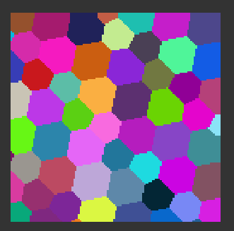
Off-center voronoi square-grid cells, and a per-pixel noise.
In the above image, I think I just interpolated triangular surfaces between peaks and then added a local noise and did something else with another offset noise that I don't really understand anymore (it's been too long since I made that and it's spaghetti code written in javascript, lol). It is overly primitive, though, and you do quickly see the grid pattern if not masked by the other noise:
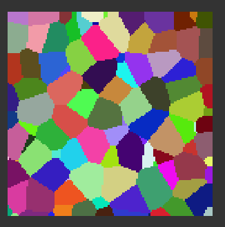
exact same but without the secondary noise
I think that in 3D, it may be more obvious. I will come back to this in a few days after making a properly rewritten 3D version of it in my own language. I cooked up a quick voronoi heightmap generator, but it's still just generating radial gradients and not at the point where it's useful for exploring different designs. Especially since my attempt at a hex grid was somehow really flawed (I just offset every second row by half a cell to the left, but that just resulted in the exact same random distribution of points). Maybe hex grids only have an impact when I use gaussian / non-uniform distributions? I guess I also need to limit the range of possible coordinates to be within a hexagonal shape, not just two independent [0,1) distributions.
JoeJ said: You have 4x4 tiles in memory. Then you can process all '2' tiles, accessing all of their neighbors. But you can not ‘1’ tiles.
Don't erosion and other post-processing effects propagate globally? Although I could simply ignore that under the assumption that the propagated effect becomes negligible across the width of a cell.
RmbRT said: Don't erosion and other post-processing effects propagate globally? Although I could simply ignore that under the assumption that the propagated effect becomes negligible across the width of a cell.
I solved how to do this last year (blog post). It involves applying fractal erosion to square tiles at power of two scales recursively. There is overlap with adjacent tiles where they share data, where overlap needs to be about the same as the number of erosion iterations (16). Information is propagated between tiles when a child tile uses data from it's parent's neighbors in the margin areas. This solves the ordering problem. You can always guarantee that a tile's parent's neighbors have already been computed before computing the tile. More results.
RmbRT said: I have a world that has to be desterministically reproducible from any starting point and is either infinite or so large that I cannot afford / do not want to generate it as a whole at any time.
Same for me, but this does not stop you from generating it offline at higher quality, compressing it, and shipping the data with the game. Almost all games do it this way. Minecraft or No Mans Sky are exceptions - the worlds are too big to store them. But you want a static world which is the same for every player, so you are not in that category and can generate offline at higher quality. If you want your world to feel real, showing a deeper meaning, cause and effect or however we name it, then offline generation is the easier way, and in in many aspects the only way. Results are just more interesting and allow more control.
RmbRT said: It is overly primitive, though, and you do quickly see the grid pattern if not masked by the other noise:
You may not see patterns visible in top down in FP view. But ofc. you can do better, avoiding the diamond patterns. I see a lot of discontinuities for example.
This is some typical voronoi noise using edge distance to generate kinda mountains or rocks:
No discontinuities, no grid alignment, and no need to access adjacency.
This is the same thing, but using distance to sample, giving randomly distributed spheres, but working for displacement or height:
No artifacts either, and that's all basic stuff very easy to do. The only problem: If you zoom out, you start to notice the domain we use to generate the random samples, as discussed above. But mixing multiple octaves of different patterns helps to hide them. You may never encounter this problem.
But you will never get something that looks like natural landscape. It will rather look like Minecraft. No mountains, no rivers, no cause and effect. No deeper meaning. It's just noise. It has no meaning. Combining multiple layers of noise does not help it.
So the usual way is to use such noises to generate an initial terrain, but then run 2D erosion simulation to turn the pointless noise into mountains and valleys. Which i did to generate this:
This is eroded noise, and it looks like mountains. I did not run some fancy tectonics simulation here, it was just random noise. The simulation takes some seconds on a single CPU core. (The professional Gaea tool does a 1024^2 simulation at higher quality in less than a second, and it's even free to use at this resolution.)
If you can't fit that into RAM because its 128k ^ 2, simulating tiles with overlap, then blending across the overlap region works well, and is still easy to implement. And you can easily ship a game with such amount of data. You may need more details still, which is usually solved with triplanar mapping of tiled textures, but using procedural texturing is an option too.
Aresseras project is very interesting here, because it does the erosion on client, which i have not seen being done before.
So, this time i want to increase your expectations, instead lowering them. ; )
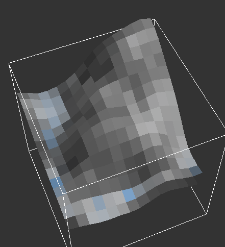
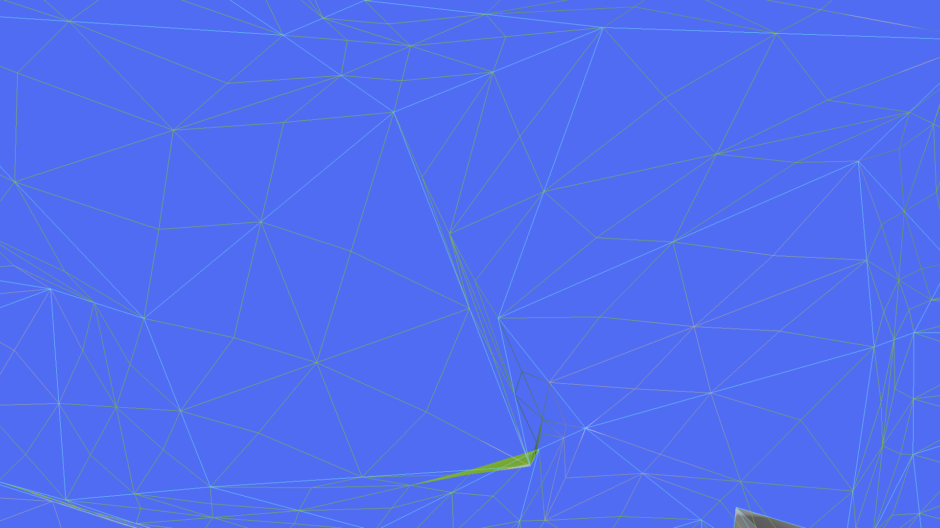
Finally got around to getting some stuff done, so here's an update. I made a mesh 3D renderer for autogenerated cells on a square grid. The placement of each peak is fully random within a cell, although I normalised the distribution for height a bit. There is no noise added on top of that for now. I then did some subdivision stuff to generate denser vertices, and added colouring based on height in my pixel shader. I had more stuff planned but didn't get around to doing much as I was mostly resting after my vacation started.
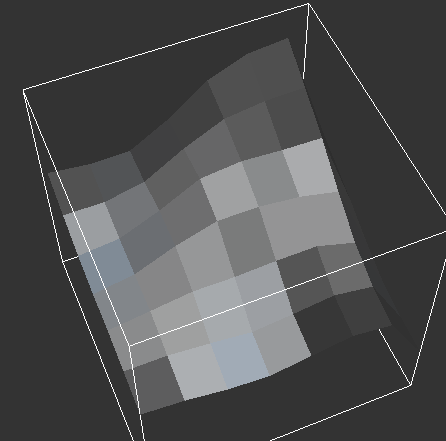
The same scene, but with the grid of center points being shown.
It's currently simply doing centerpoint subdivision with an average height of all surrounding cells' center points, and then one further level of subdivision, to get better shapes.
The macroscopic landscape features aren't super terrible, but I obviously want to make them better. I especially want to add different modes of cell subdivision based on whether neighbouring peaks have a “connection” or not (decided by relational noise). So that I have some lone peaks next to each other or maybe hills or valleys, or some that are connected so that they form more of a straight line between their center points as seen by the mountain here. But it seems like this “connected” mode gives more natural results than individual voronoi peaks, so I'll have to look into how to balance both modes. But first, I have to implement that isolated cell mode where each cell is a mountain peak and the height is more based on the distance from the cell border.
RmbRT said: Finally got around to getting some stuff done, so here's an update.
Looks pretty nice. Reminds me on the landscapes of the Magic Carpet game. : )
RmbRT said: The placement of each peak is fully random within a cell, although I normalised the distribution for height a bit.
It's an interesting choice to jitter the vertices in all directions. Has rarely been done. Though, there are some good reasons to avoid this, and maybe you have not thought of them. If you do this, you increase complexity for systems such as LOD or collision detection. It will cost you dev time and performance. Maybe you could even use twice the resolution for the same performance, when keeping the vertices quantized to the grid like standard heightmaps do, and all algorithms would be much simpler as well. Also, the advantage to move vertices in all direction is quite limited, since your edges are still coarsely constrained by a global grid, which itself is not aligned to the curvature of the geometry. So you do not really solve a problem this way, just hide it a bit better than otherwise.
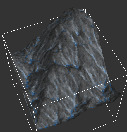
But that just said to add some context, illustrating a decision you do now has big impact on the things you'll have to do later. I can show some images from my 3D erosion sim again to show how standard heightmaps look in comparison, and how resolution affects the results:
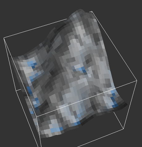
That's 128x128. Halfing resolution for each following image…
Unfortunately i have no smooth shading to hide it, but the global grid is surely much more visible than with your jittered mesh. So the question is likely: At which higher resolution does the simple heightmap look better than your jittered grid, and at which lower resolution does the jitter add enough variety to be worth it? Hard to say ofc.
I guess you want some large scale mountains and deeper valleys. Currently it's everything at the same height, and the landscape looks flat and thus the same everywhere. I would propose fbm noise, which is pretty good to model mountains, clouds, etc. The idea is to recursively add higher frequencies with lower amplitudes. Really useful, simple and fast. Gives something like that without any erosion:
That's usually the starting point for all those nice procedural terrain demos, shadertoys, etc., and iq's webpage explains it well.
RmbRT said: So that I have some lone peaks next to each other or maybe hills or valleys, or some that are connected so that they form more of a straight line between their center points as seen by the mountain here.
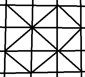
Maybe i can narrow this topic down a bit… You work with a regular grid, so your topology is constrained to quads (i use those quad normals for shading, exposing this grid). But you use triangles for the final geometry. Which means you talk about the problem of triangulating a quadmesh, giving only two options per quad:
Either the green split or the red split. That's all you can do. For height map rendering it's common to use just one option for the whole mesh, for simplicity and performance. But ofc. that's not ideal. Another common option is to use this kind of alternating diagonals generating a diamond pattern:
That's still simple, and usually better, because it expresses both ways to express curvature. It gives a second, larger grid rotated 45 degrees.
If that's still not good enough, we can choose for each triangle individually. The most common method is Delaunay Triangulation, but since we are constrained to the global grid and most edges are fixed, we can apply it only to the choice of the diagonal. And if our landscape is pretty flat, Dalaunay can often not really tell us which is better. (Similar to the even simpler method of just picking the shorter diagonal, which is usually a decent choice but in this case fails too because both diagonals may have the same length.)
For artworks, i often was angry about modeling tools triangulation results on quad meshes. I guess most of them use Delauney, but i had to pick and rotate many edges manually for better results. So i was asking myself: How can we do better than this?
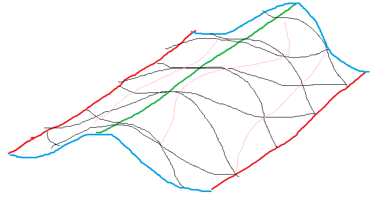
My idea was to consider curvature, which all the methods mentioned so far do completely ignore. And recently i have implemented it, to use my quad meshes as triangle colliders for the physics engine. But unfortunately i can't make images from that easily now, so i'll try to draw an example instead:
The red, green, blue lines illustrate the geometry, actually a simple bump. The black lines show a quad grid tessellation of that, but the grid is rotated 45 degrees so the edge flow disagrees with the curvature flow, which always is the central problem here.
The pink lines show the ideal choice of diagonals to form triangles, which agrees much better with the curvature than to other way around would do. If we do the wrong choice, the mesh appears jaggy, not smooth, and low quality. Delaunay would pick all the wrong diagonals here. It would fail, because it ignores curvature. It considers only a local patch of geometry, assuming it would be flat. So it makes the wrong choice. It is not as ideal as many people think it is. Actually, it is only ideal for flat 2D meshes.
However, considering curvature is not trivial. Personally i do it by calculating the primary direction of curvature, but since that's actually a line not a vector, we can not just sum up normals or something simple like that. Some higher math is needed. I can elaborate more and post code if you're interested, but actually i only want to give the idea about those concepts. When you talk about ‘connecting things to form mountain ridges’, you may not yet be aware that those problems can be modeled well automatically this way, and then it all depends on just the height data. But just saying - you may have something else in mind to model it in a more explicit way.
JoeJ said: It's an interesting choice to jitter the vertices in all directions. Has rarely been done. Though, there are some good reasons to avoid this, and maybe you have not thought of them. If you do this, you increase complexity for systems such as LOD or collision detection. It will cost you dev time and performance. Maybe you could even use twice the resolution for the same performance, when keeping the vertices quantized to the grid like standard heightmaps do, and all algorithms would be much simpler as well.
I am actually going to do exactly that. I just use peaks that are randomly placed, and for now, in order to avoid having a detailed mesh, I just do some subdivision. This is just an approximation and will be replaced with a normal mesh, because in the end, it doesn't make much of a difference. I still need to sample the height on a finer grid for the different LODs, and for simple collision etc. I think I'll keep the randomly spread-out approach for more macroscopic features until I arrive at a fine level of detail, and then put that into a regular grid. It will nonetheless be a pain to rasterise that. I have done cosine interpolation on a grid before, but it always looked stupid.
Although I guess I can use the dot product to see how far along I am at two opposing edges of the cell, and then average that or interpolate the two values of that by how far along I am at the average of the other two opposing edges, to scale the thing back into some kind of sane 2d coordinate system. I'll have to try that out, it seems promising. Because if I have a proper coordinate system that always goes [0,1], I can easily check in which quadrant etc. I am and do some special logic based on whether I'm closer to an edge, a corner, or the midpoint. I bet that will be a bit more complicated to get working for concave cells, though.
Another thing that would be cool for collision is to use a separate u8 or u16 grid (square) of height offsets from some base height value, and with the maximum magnitude difference within the chunk as scale, which samples the height at regular intervals in a geometry chunk (square), and then I just need to interpolate linearly between the 4 edge points. That could be pretty compact. u8 should be perfectly sufficient if chunks aren't large, like for example 64*64 meters, I'd still get quite a bit of accuracy. Unless the chunk has a cliff face running through, LOL. But even in those cases, u16 should be more than enough. Saves me memory and cache misses.
My subdivision looks like this (it's a bit hard to see the blue lines, but those are the connections of the cell peaks, and the grey lines are the subdivided geometry):
It was especially tricky to do the subdivision correctly for concave cells, since the average / midpoint lies outside the shape and resulted in geometry that was facing downwards. I basically did a check for each corner whether it was concave, and if so, I did not use the average point, but instead chose the midpoint between the concave corner and its opposite corner (since only up to one corner can be concave).
JoeJ said: However, considering curvature is not trivial. Personally i do it by calculating the primary direction of curvature, but since that's actually a line not a vector, we can not just sum up normals or something simple like that. Some higher math is needed.
Yes, curvature initially was biting me. I think my approach works fine for now at that level of detail, and I'll probably be using something derived from that in my higher detail versions.
JoeJ said: I can elaborate more and post code if you're interested, but actually i only want to give the idea about those concepts. When you talk about ‘connecting things to form mountain ridges’, you may not yet be aware that those problems can be modeled well automatically this way, and then it all depends on just the height data. But just saying - you may have something else in mind to model it in a more explicit way.
Thanks, I'll ask if I ever get hopelessly stuck, which is hopefully never! But I did start out with a square grid of interpolated points and it sucked exactly at ridges. But at this low of a LOD, I can simply not rasterise it into a mesh, and instead directly model mountains or voronoi borders with triangles. I had a few previous terrain generation projects where I think I also solved the problem somehow, I don't exactly remember how anymore, though, so I'll have to get creative when I arrive at the final rasterised mesh. Maybe it will simply be a smoothed version or something and then the ridges simply will not be sharp. Or I will have to use irregular meshes until the bitter end, and only use regular meshes for collision.
For now, the next steps are to add different types of cell triangulation with the secondary relational noise to decide whether to do border-based or peak-based triangulation between two peaks. I'm not sure yet how to decide the elevation for borders, though; those could be either all fixed at 0 or maybe based on some really low-frequency noise, or based on distance to the peaks and their height (slope-based), idk.
RmbRT said: Thanks, I'll ask if I ever get hopelessly stuck, which is hopefully never!
The problem is not that we get stuck, but that we tend to explore wrong paths which feel promising at first, but later becoming a dead end in the moment we decide to work on alternatives instead. For me at least. If only i knew in advance which paths are dead ends…
If i understand your post correctly, you want to model the coarsest representation of your world using the mesh consisting of jittered grid vertices. After that You want to project it to a higher resolution heightmap, which you then may refine with details and using it for rendering and physics.
Actually i have doubts regarding the first step. Why do you model using a mesh? Why not just a lower res mip map level of the final heightmap? If you want to use conventional height maps in the end anyway, there is no point to work with a mesh. Meshes suck! They are evil! Working with plain simple images is so much easier, and even more so if we do it procedurally.
I feel the need to help you avoiding a dead end. Maybe you think the edges present in the mesh help to model the ridge of a mountain, or a river, etc.? That's really wrong if so. You always need to know where the ridge is before you can create an optimal mesh from that model. The model must already exist, and meshes then are our final output. It's the last step in the pipeline, not the first. It's the last step because meshes are evil! : )
That's no joke. I'd love to know your reasoning for using a mesh to generate procedural heightmaps…
The thing about just using a LOD image is that if only represents magnitudes at the center of each sample. But I want the samples themselves to be irregularly distributed, so that I have peaks and valleys that are not on a uniform grid. And I'm not going to make a triangle mesh and then try to apply noise heightmaps to that. This is just the easiest way for now to visualise it. I have no plans to explore mesh manipulation techniques. I will just keep modeling the landscape using the cells' centerpoints (peaks and valley centers), and continue from there. But I admit that my approach of non-uniform sample locations means that when I finally have to make uniform samples out of it, it will become more complicated to make that transition. But it's not as bad as having 3D triangle data and wanting to work on that.
I think that this approach will have different results compared to normal multi-layer noise with evenly spaced sampling & power frequencies.