
Subdivision landscaping ~ pt. 1: modeling & rendering

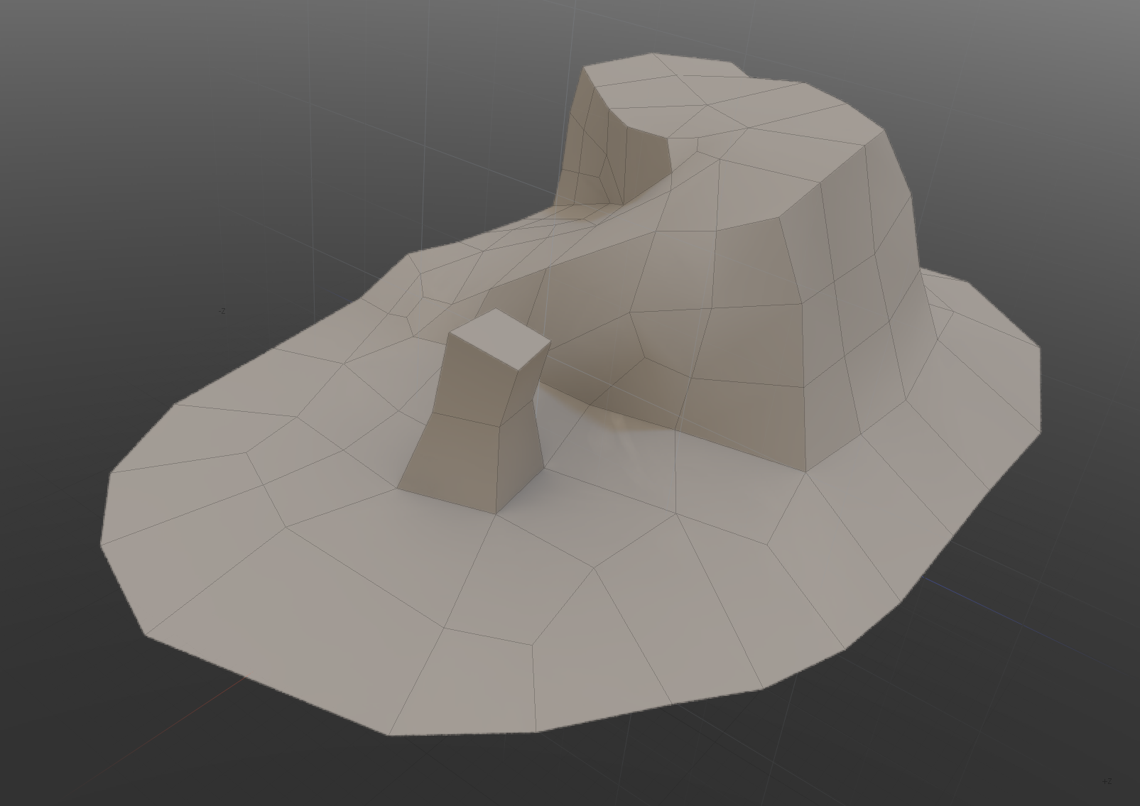
For this project (an RTS game) I wanted to see if I could model all level terrain as a subdivision mesh.
I did try this before, but ran into the issue of the terrain appearing too lo-res and featureless in-game and textures not looking great around UV seam areas:
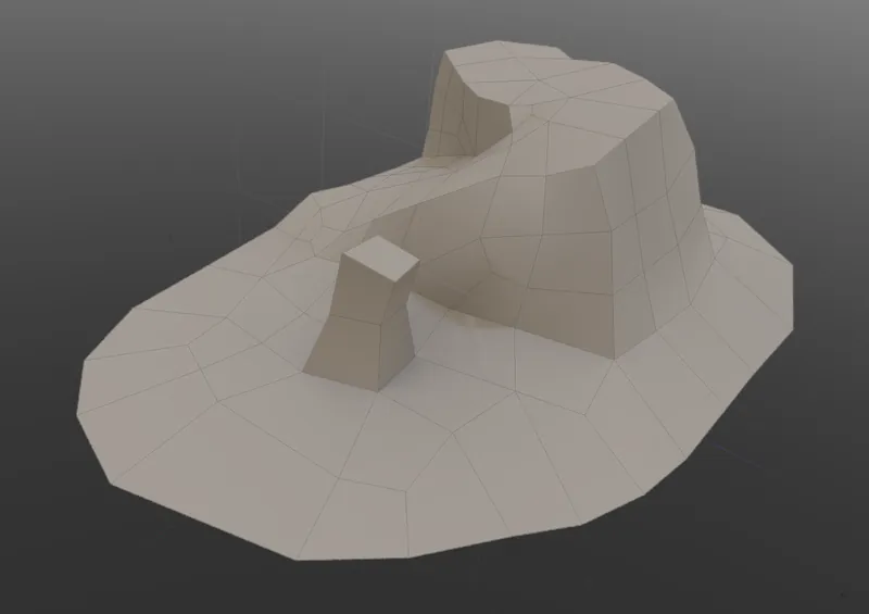
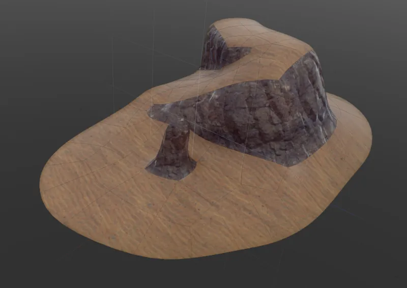
These manifold quad meshes do have some nice properties though - because they're very grid-like, they work well as-is as navmeshes and can be used for fast signed distance lookups, things I both needed for pathfinding and collision detected, so I wanted to give this another look.
Most obviously I was being too conservative with geometry. I also added support for SubD creases to bring back some of the edge features of the cage mesh:
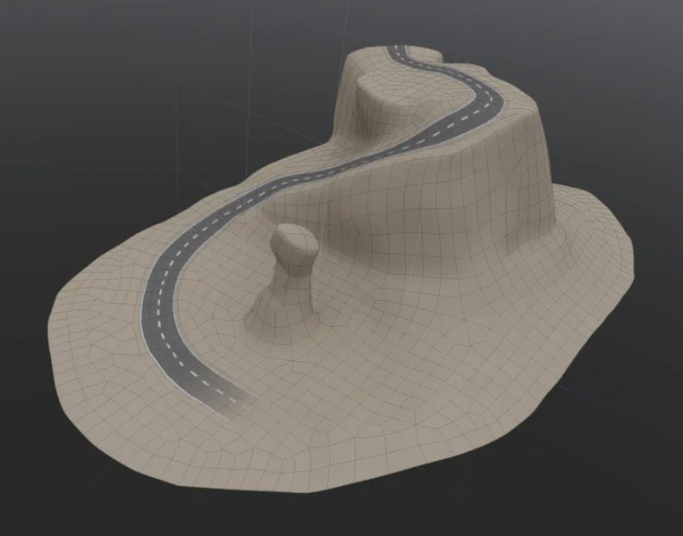
Tessellation and displacement mapping felt like the best option to add more geometric detail. Similarly to heightfield tessellation I diced the landscape up into smaller patches - in this case each individual face expands into its own patch. In a compute pass each face gets assigned a LOD level based on its proximity to the camera and then rendered as a square grid of vertices.
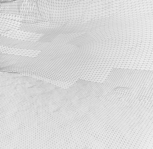
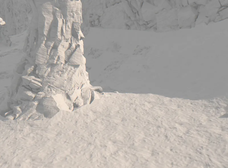
Tri-planar mapping could solve the texture discontinuity problem, but I prefer to use UV mapping, as the former can quickly look repetitive and these projection don't work well with features such as 45 degree hills and the sides of slopes - UV maps give you far more control.
So instead I do a reprojection/unwrapping of all vertices and edges that lie on a chart border, into their neighboring charts - effectively expanding UV charts by one face:
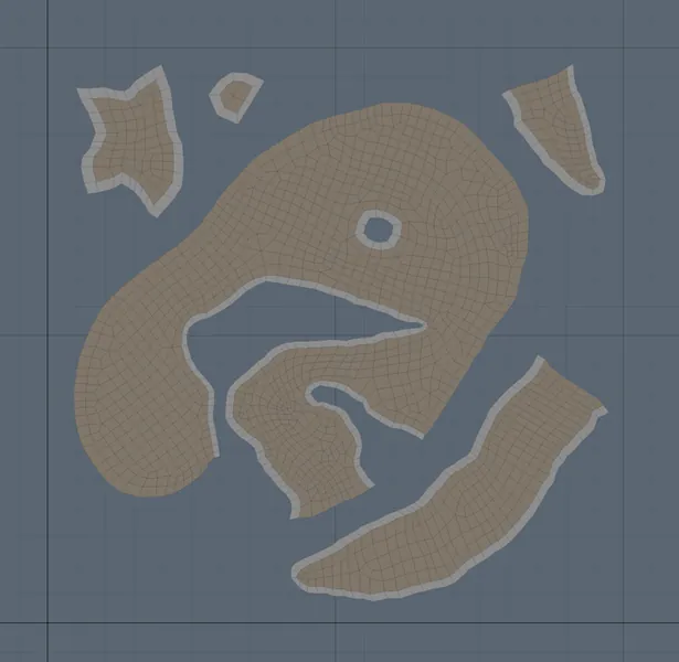
Within these expanded UV regions I can smooth over all boundary discontinuities.
It turns out, as with tri-planar mapping, this always takes three texture lookups. That's only around UV borders though - in regions where there's no discontinuity, all three UV projections will sample the same texels.
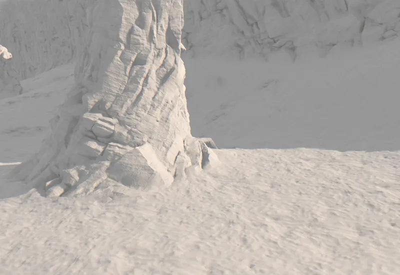
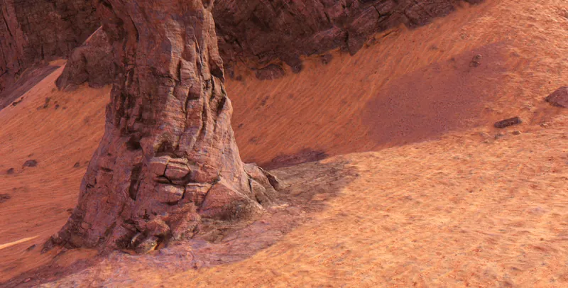
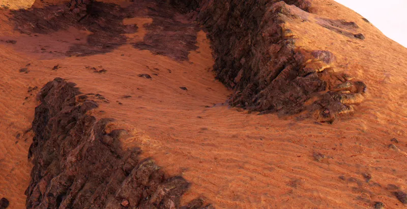
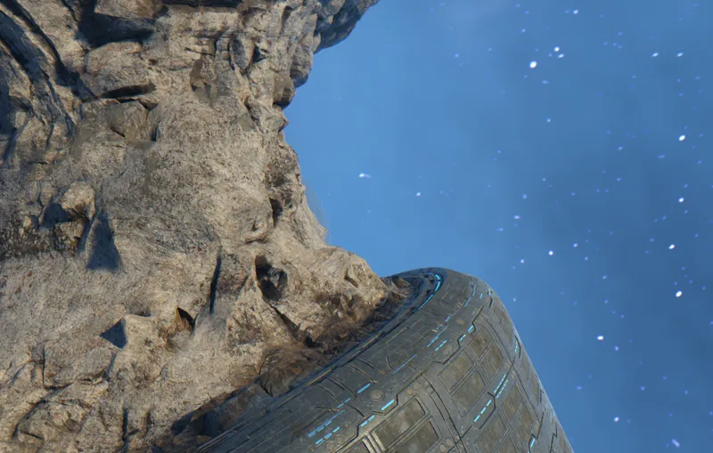
So I'm glad I gave this another try, as I find I do prefer this landscape-as-a-mesh workflow.
Next up: collision detection and pathfinding
bye
Discussion