
Real-Time Realistic Cloud Rendering and Lighting
Describes 3D volumetric cloud rendering using Harris' method for lighting.
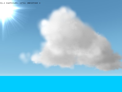 Get the source code for this article here. 1. Introduction As a ray of light travels through a medium, the radiance, commonly called the intensity, may change depending on the contents of the medium. A medium which affects the radiance of light is called a participating medium and such a medium can influence light in several ways. Scattering of light happens in a vast variety of environments and is used in creating visual effects such as: atmospheric haze, sky-light computation, light passing through clouds or smoke, light passing through water and sub-surface scattering. These effects are very complex and usually require large amounts of computation due to the mathematical functions that need to be evaluated. For the purpose of real-time computer graphics, scattering algorithms are often simplified and adapted to run on graphics hardware. Another option is to allow artists to setup functions and parameters that mimic real light scattering, thus saving computation time. 2. Harris' Model for Cloud Rendering and Lighting The solution proposed by Harris is to approximate the scattering integral over the volume of the cloud using graphics hardware to speed up the process. The basic ideas are
 - The radiance absorbed in each cloud volume unit, modeled as a metaball, is stored in a texture which is used for splatting.
- The product which approximates the integral is calculated by reading from the draw buffer the previous splat result and using it for the current splat which is blended back into the buffer.
- Two scattering directions are used: from the sun to the cloud center and from the eye point to the cloud center. This accounts for most of the light scattered in the cloud.
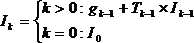 This equation relates the intensity of the current particle I[sub]k[/sub] with the intensity of the previous particle I[sub]k-1[/sub] and the transparency of the previous particle T[sub]k-1[/sub]. The other term is g[sub]k-1[/sub] where g[sub]k[/sub] = a[sub]k[/sub] x ?[sub]k[/sub] x p(l, -l) x I[sub]k[/sub] x ?/4?. As we can see g[sub]k-1[/sub] is related to the intensity of the k-1 fragment so we will have to read this value from the frame buffer. All the other values in the equation (albedo, extinction, solid angle) are constants and the p(l, -l) element is a phase function which will be discussed later. The original intensity I[sub]0[/sub] is fully bright thus the buffer is first cleared to white. This equation can be encoded for graphics hardware through blending. Blending calculates the sum of the incoming fragment multiplied with the "source factor" and the existing fragment in the buffer multiplied with a "destination factor". In our case the source factor is 1 (as g[sub]k-1[/sub] doesn't have any coefficient) and the destination factor isT[sub]k-1[/sub], the transmittance of the fragment in the splat texture. The result of the blend operation is a color which is then read back for the next particle. Since opacity is stored in the splat texture, transmittance T[sub]k-1[/sub] will equal one minus opacity. This gives the blend function with parameters GL_ONE, GL_ONE_MINUS_SRC_ALPHA. A rough description of the lighting process can be formulated: we start from a fully bright buffer and use the splat textures to decrease the luminance thus "darkening" the color of the particles as they get farther from the light. We start by looping over the particles and calculating the screen position of it's center using projection: double CenterX, CenterY, CenterZ; gluProject(Cloud->Puffs.Position.x, Cloud->Puffs.Position.y, Cloud->Puffs.Position.z, mm, mp, vp, &CenterX, &CenterY, &CenterZ); (note: here the puffs were in world space) The, using the solid angle over which we will read back the pixels from the buffer, the size of the splat buffer and the cloud radius we compute the area which will be read: Area = Cloud->Puffs.DistanceToCam * SolidAngle; //squared distance Pixels = (int)(sqrt(Area) * SplatBufferSize / (2 * Cloud->Radius)); if (Pixels < 1) Pixels = 1; ReadX = (int)(CenterX-Pixels/2); if (ReadX < 0) ReadX = 0; ReadY = (int)(CenterY-Pixels/2); if (ReadY < 0) ReadY = 0; buf = new float[Pixels * Pixels]; //we only need the red component since this is greyscale glReadBuffer(GL_BACK); glReadPixels(ReadX, ReadY, Pixels, Pixels, GL_RED, GL_FLOAT, buf); Finally we compute the average intensity in the area and calculate the color of the current particle which will be splatted, following the equation above. avg = 0.0f; for (j = 0; j < Pixels * Pixels; j++) avg += buf[j]; avg /= (Pixels * Pixels); delete [] buf; //Light color * // average color from solid angle (sum * solidangle / (pixels^2 * 4pi)) // * albedo * extinction // * rayleigh scattering in the direction of the sun (1.5f) // (only for rendering, don't store) factor = SolidAngle / (4 * PI); ParticleColor.R = LightColor.R * Albedo * Extinction * avg * factor; ParticleColor.G = LightColor.G * Albedo * Extinction * avg * factor; ParticleColor.B = LightColor.B * Albedo * Extinction * avg * factor; ParticleColor.A = 1.0f - exp(-Extinction); This color, stored in ParticleColor will be stored as the color which will be used for rendering later on, but when we are splatting the particles for lighting we need to include the phase function. This is always equal to 1.5 in the direction of the light so we scale up our color by this value before rendering this particle as a billboard. 4. The phase function - Scattering in the eye direction To simulate multiple scattering in the eye direction a phase function is used. The phase function allows the calculation of the distribution of light scattering for a given direction of incident light. The phase function takes as parameters two directions, in our case the light direction and the direction of light arriving at the observer. Thus, when doing lighting, the direction of incident light is the negative of the direction of the light. When rendering normally the direction the light arrives at the observer is the vector between the particle position and the camera eye point. The function Harris uses is a simple Rayleigh scattering function:
  Where ? is the angle between ? and ?' and thus equal to their dot product if they are normalized. When ? is in the direction of ?' the function is equal to 1.5 giving the value used in lighting. 5. Creating Cloud Impostors To speed up rendering, the 3D clouds, composed of particles, can be rendered to a 2D surface which is then mapped onto a billboard. This saves fillrate as the impostor is only updated when the change in angle between the camera and the cloud center exceeds a certain threshold. The hardest part in rendering the impostor is setting up the camera. In this case the camera will lie at the eye position and will point at the cloud center. The particles are sorted back to front to eliminate transparent blending problems. Setting up the camera is easily done with OpenGL's functions and again we will use an orthographic projection. glMatrixMode(GL_PROJECTION); glPushMatrix(); glLoadIdentity(); glOrtho(-Cloud->Radius-pr, Cloud->Radius+pr, -Cloud->Radius-pr, Cloud->Radius+pr, d - r, d + r); glMatrixMode(GL_MODELVIEW); glPushMatrix(); glLoadIdentity(); gluLookAt(Camera.x, Camera.y, Camera.z, Cloud->Center.x, Cloud->Center.y, Cloud->Center.z, 0, 1, 0); glPushAttrib(GL_VIEWPORT_BIT); glViewport(0, 0, ViewportSize, ViewportSize); The viewport size can be set to trade between speed and quality. A more advanced implementation will set the viewport size depending on the distance of the cloud center to the camera. After the viewport is set up we can simply render the particles with their respective colors as billboards. Again we will enable blending and set the blend function to GL_ONE, GL_ONE_MINUS_SRC_ALPHA. The up and right vectors for the billboards can be obtained straight from the modelview matrix as such: float mat[16]; glGetFloatv(GL_MODELVIEW_MATRIX, mat); Vector3 vx(mat[0], mat[4], mat[8] ); Vector3 vy(mat[1], mat[5], mat[9] ); When rendering each cloud particle we have to calculate the phase function and modulate the particle color with it: costheta = Dot(Omega, Light); phase = 0.75f * (1.0f + costheta * costheta); Now we can upload the frame buffer into a texture which will be used for creating the cloud billboard: glBindTexture(GL_TEXTURE_2D, Cloud->ImpostorTex); glCopyTexImage2D(GL_TEXTURE_2D, 0, GL_RGBA8, 0, 0, ViewportSize, ViewportSize, 0); Now the cloud can be simply rendered as a billboard with the texture we uploaded. To detect when an impostor update is needed we store the vector from the cloud to the camera of the last update and compute the angle between it and the current vector. float dot = Dot(ToCam, Clouds.LastCamera); bool in_frustum = Frustum.SphereInFrustum(Clouds.Center, Clouds.Radius); int mip_size = GetImpostorSize(SqDist(Camera, Clouds.Center)); if ((dot < 0.99f || Clouds.ImpostorSize < mip_size) && in_frustum) { RenderCloudImpostor(&Clouds, Sun, Camera); Clouds.LastCamera = ToCam; } 6. Creating the Splat Texture The splat texture that we use encodes the intensity of light lost as the light passes through the cloud particle's volume. Thus, as less light passes through the center than through the edges, the texture needs to exhibit a falloff from the center to the edges. To our aid comes a nice interpolating polynomial which, using an interpolant between 0 and 1, varies from 1 to 0 in a smooth way. Since we are interpolating between a value in the center of the texture and 0 on the outside, the polynomial can be further simplified to give a function of the center value and the interpolant.
  v[sub]1[/sub] can be chosen arbitrarily to give a good result and f is the distance between the pixel we are coloring and the center divided by the radius of the texture. Instead of computing the distance in pixels we can have variables which vary from -1 to 1 from left to right, top to bottom on the texture and thus also eliminate the need for division by the texture radius. Y = -1.0f; for (int y = 0; y < N; y++) { X = -1.0f; for (int x=0; xfloat)sqrt(X*X+Y*Y); if (Dist > 1) Dist=1; value = 2*Dist*Dist*Dist - 3*Dist*Dist + 1; value *= 0.4f; B[j+3] = B[j+2] = B[j+1] = B[j] = (unsigned char)(value * 255); X+=Incr; } Y+=Incr; } 7. From Impostors to Full 3D Models A visual improvement can be obtained by changing between rendering impostors and rendering the full 3D cloud. This helps when objects pass through clouds as they won't simply show up as clipping the cloud impostor billboard but they will appear to really travel through the cloud. First of all we need to determine below which distance the cloud should look fully 3D and above which distance the cloud should appear only as an impostor taking into account the size of the cloud. Through experimentation good values for these distances are 2 times the radius of the cloud and 4 times the radius respectively. In between these distances we will fade the impostor out from fully opaque to fully transparent. The 3D will also be faded but it will go from transparent to opaque as the camera draws nearer. To calculate the alpha value when the impostor and the 3D model are fading we use: alpha = (Clouds.DistanceFromCamera - dist_3D) / (dist_impostor - dist_3D); The main problem is that the texture already contains an alpha channel and we need to blend it with the GL_ONE, GL_ONE_MINUS_SRC_ALPHA factors. Thus we cannot simply use the alpha value of the color to fade. Setting the all the components of the color to the color will achieve this. Thus in the impostor rendering function we use: glColor4f(alpha, alpha, alpha, alpha); The 3D rendering function looks very similar to the impostor creation function, excluding the viewport and camera changes. To fade the particles we must multiply their colors by the alpha value and then send it to OpenGL. ParticleColor.R = (0.3f + Puff->Color.R * phase) * alpha; ParticleColor.G = (0.3f + Puff->Color.G * phase) * alpha; ParticleColor.B = (0.3f + Puff->Color.B * phase) * alpha; ParticleColor.A = Puff->Color.A * Puff->Life * alpha; The conditions for determining which way to draw the cloud are: //beyond this render only the impostor dist_impostor = Clouds.Radius * 4; //square this since the camera distance is also squared dist_impostor *= dist_impostor; //closer than this render only the 3D model dist_3D = Clouds.Radius * 2; //square dist_3D *= dist_3D; if (Clouds.DistanceFromCamera > dist_impostor) RenderCloudImpostor(&Clouds, 1.0f); else if (Clouds.DistanceFromCamera < dist_3D) RenderCloud3D(&Clouds, Camera, Sun, 1.0f); else { alpha = (Clouds.DistanceFromCamera - dist_3D) / (dist_impostor - dist_3D); RenderCloudImpostor(&Clouds, alpha); RenderCloud3D(&Clouds, Camera, Sun, 1.0f - alpha); } 8. Conclusion Harris' method for cloud rendering is suitable for real-time applications requiring a realistic model for clouds which one can fly through. With the added advantage of impostors the performance is good even for a large number of clouds. However the method does present some disadvantages:
 - If the light direction changes the whole lighting algorithm has to be executed again which is expensive if it is to be done in real-time. This can be alleviated by distributing the calculations over several frames and storing intermediate results in a separate texture. Loading the texture from the framebuffer is a rather inexpensive operation and can be performed each frame to store the calculations. Another advantage of using such a texture is that it can be used as a lightmap, projecting it on geometry underneath to achieve correct shading.
- The time required by the lighting algorithm is significant and for many clouds the processing time can slow down the loading of the game. This is however a fair trade-off for having realistic clouds.
- Using the splat texture the clouds always look very fluffy, there is a lack of detail. Niniane Wang proposes a different, artistically based method, used in Microsoft Flight Simulator 2004, which gives better detail on the clouds and uses less particles which comes as a trade-off to physically correct lighting.
Related Tutorials
Balancing Game Development and Creative Direction in Indie Production
A practical look at how indie developers can balance creative direction with hands-on game development. This article co…
 huseyin_onur
My Unreal Engine Development Process: From Core Idea to Playable Build
A practical overview of my Unreal Engine development process, covering how I move from a core game idea to a playable b…
huseyin_onur

Introducing LaneGraph: The Ultimate Road Network Solution for Unity
Discover the power of LaneGraph, a lightweight and flexible lane-based navigation system for Unity. LaneGraph makes it…
Retargeting Mixamo Characters with Root Motion In Unreal Engine 5.4.
I have always found Retargeting Mixamo Characters To have Root Motion is a serious lengthy Tast, Recently I stumbled up…

How To Make A SIMPLE Main Menu In Unity
In this tutorial for unity, i go over how to make a simple main menu for unity, it's an unlisted video because i do not…
 FlipThaSwitzh

Guide to Gameplay Balance
A perspective on competitive gameplay balance, from a background of "shooter" sandbox design.
 Tucker933
Discussion
More from Andrei Stoian
Comparing Shadow Mapping Techniques with Shadow Explorer
New Incentives and a Whole New Platform From The Intel AppUp developer program
The final installment in this series on Intel's AppUp program details additional incentives and opportunities for devel…
The Game Maker
This book excerpt contains the first chapter of the book that introduces beginning game developers to the Game Maker pr…
Discussion