Introduction to Occlusion Culling
Object culling is a very important facet of graphics programming. It is incredibly wasteful and time consuming to render objects that are not even going to be visible to the user. However, it is critical to optimize the culling process itself. Often, it can use up a lot of processing time instead of saving it.
Even though the culling process needs to be optimized to every extent possible, numerous traditional methods, which have proven themselves to be fast and adequate enough for standard situations, leave much to be desired. Some cull too many objects, and others do not perform enough culling.
The theory of occlusion culling spawns from the fact that even though an object is inside the camera frustum, it could still be hidden and out of view.
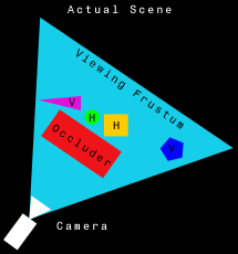
Diagram 1.1: Example scene layout
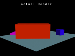
Diagram 1.2: Example scene render Here, as Diagram 1.1 shows, five primitives are displayed in a scene. However, in the final render (Diagram 1.2), only 3 of them are actually visible. Even though those other two objects turn out to be hidden, they are still rendered, wasting a lot of time. A simple frustum-based culling procedure would still result in the objects being rendered, since they are inside the camera's view.
Occlusion-based culling procedures are used to determine which objects will actually be visible. Only those objects will actually be rendered, thus saving loads of time. An occluder is an object that hides other objects (for example, the large red box in Diagram 1.1). Half-occluded objects are partly visible (the blue pentagon and purple wedge), and are still rendered. Fully-occluded objects are completely hidden (the green sphere and orange box), and are excluded from being rendered.
For more background information on occlusion culling, please refer to Occlusion Culling Algorithms, by Tomas M?ller and Eric Haines.
Introduction to IDirect3DQuery9
The IDirect3DQuery9 interface is one of the new features of DirectX9. It allows developers to access a wealth of statistics, including optimization information, objects handled by the resource manager, and triangle processing.
IDirect3DQuery9 can also perform occlusion queries, which calculate the number of pixels visible on the screen. Only pixels that were rendered between the query start and the query finish are included in this count. If the result is zero, the vertices rendered are fully occluded, meaning they are not visible from the current camera position. So, if the occlusion result is greater than zero, the vertices rendered are visible to the user.
Query Type Datatype Use D3DQUERYTYPE_VCACHE D3DDEVINFO_VCACHE Information about optimization, pertaining to data layout for vertex caching D3DQUERYTYPE_RESOURCEMANAGER D3DDEVINFO_RESOURCEMANAGER Number of objects sent, created, evicted, and managed in video memory D3DQUERYTYPE_VERTEXSTATS D3DDEVINFO_D3DVERTEXSTATS Number of triangles that have been processed and clipped D3DQUERYTYPE_EVENT bool For any and all asynchronous events issued from API calls D3DQUERYTYPE_OCCLUSION DWORD The number of pixels that pass Z-testing, or are visible on-screen. Table 2.1: Uses of IDirect3DQuery9 The ATI Occlusion Query demo conveys the basics of IDirect3DQuery9 implementation.
Occlusion Culling with DirectX9
The emergence of IDirect3DQuery9 provides an easy way to implement effective occlusion culling. The basic process is presented below:
- Render every object's bounding mesh
- For every object:
- Begin query
- Re-render the bounding mesh
- End query
- Retrieve occlusion query data. If the pixels visible are greater than zero, the object should be rendered. Otherwise, the object should be occluded from rendering.
Step 1
The actual mesh contains too many vertices to use in the occlusion culling process, so a bounding mesh, with a much lower vertex count, will be used as a substitute. Why use a bounding mesh instead of a bounding box or sphere?
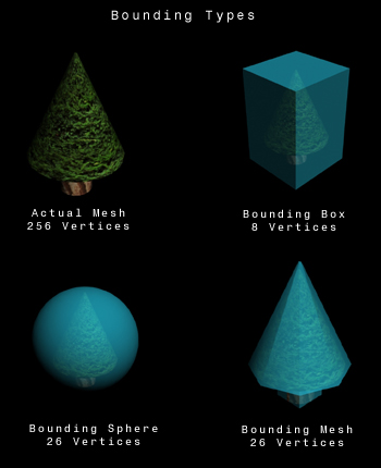
Diagram 3.1: Types of bounding volumes Diagram 3.1 shows multiple types of bounding volumes, including box, sphere, and mesh. Note that the number of vertices of the sphere and mesh are the same, in this particular case. However, even though the vertex count is close, the fit of the volumes drastically varies. The bounding mesh is the only volume that truly approximates the original mesh well enough to be accurate. This is very important in the occlusion process, as a large amount of vertices may be mistakenly rendered or excluded based on their bounding volume.
However, a bounding mesh cannot be calculated through an algorithm like a bounding box or mesh can. It needs to be modeled and loaded at runtime, just like a normal mesh.
Each object's bounding mesh is rendered first to make sure the entire scene is present in the Z-buffer. If the occlusion query were to take place before all the objects were present in the Z-buffer, then the object being queried could mistakenly be found to be visible, even though it would actually be occluded in the final scene.
Step 2
Now that every object's bounding mesh is in the Z-buffer, the same thing must be done again, except this time, the occlusion query is used to determine each object's visibility status. If the query finds zero visible pixels, the object is excluded from the final, full-scale rendering. If the query finds one or more visible pixels, the object is included in the render.
It is important to note that the occlusion cull rendering does not take place on the primary, full-size surface. A much smaller surface (320 pixels by 240 pixels seems to work well) is used to improve performance.
The Code
Type Declarations
SObject (Code Listing 4.1) is the main object entity. CMesh is a class that encapsulates the loading, rendering, and release of an ID3DXMesh interface.
struct SObject { CMesh* meshReference; // Reference to a mesh object CMesh* boundingMesh; // Reference to low-poly bounding mesh D3DXVECTOR3 pos; // Position of this object D3DXMATRIX matTranslate; // Translation matrix for this object bool render; // If true, render the object float distanceToCamera; // The distance to the camera (player position) // Constructor SObject( CMesh* meshRef, CMesh* boundMesh, D3DXVECTOR3 position ) { meshReference = meshRef; boundingMesh = boundMesh; pos = position; render = false; distanceToCamera = 0.0f; } }; Code Listing 4.1: SObject definition
Object Declaration
For the occlusion process, interfaces of LPDIRECT3DQUERY9, LPD3DXRENDERTOSURFACE, LPDIRECT3DSURFACE9, and LPDIRECT3DTEXTURE9 need to be declared.
LPDIRECT3D9 d3dObject; // Direct3D Object LPDIRECT3DDEVICE9 d3dDevice; // Direct3D Device LPDIRECT3DQUERY9 d3dQuery; // The occlusion query LPD3DXRENDERTOSURFACE occlusionRender; // Occlusion's render to surface LPDIRECT3DSURFACE9 occlusionSurface; // Occlusion's surface that it uses LPDIRECT3DTEXTURE9 occlusionTexture; // Texture to get surface from std::vector objects; // Vector of objects
Code Listing 4.2: Declarations of objects pertaining to the occlusion culling procedure
Setting up the Occlusion Objects
The query itself must be created, along with the texture and the render-to-surface. D3DUSAGE_RENDERTARGET is used during the creation of the texture, since it will be rendered to. The surface itself is obtained through the GetSurfaceLevel() function of LPDIRECT3DTEXTURE9. A Z-buffer format of D3DFMT_D16 is used for the LPD3DXRENDERTOSURFACE interface, as it will be needed for use.
//----------------------------------------------------------------------------- // Name: SetupOcclusion() // Desc: Create the objects needed for the occlusion culling //----------------------------------------------------------------------------- HRESULT SetupOcclusion() { // Create the query d3dDevice->CreateQuery( D3DQUERYTYPE_OCCLUSION, &d3dQuery ); // Get the display mode to obtain the format D3DDISPLAYMODE mode; d3dDevice->GetDisplayMode( 0, &mode ); // Create the texture first, so we can get access to it's surface if( FAILED( D3DXCreateTexture( d3dDevice, 320, 240, 1, D3DUSAGE_RENDERTARGET, mode.Format, D3DPOOL_DEFAULT, &occlusionTexture ) ) ) { return E_FAIL; } // Obtain the surface (what we really need) D3DSURFACE_DESC desc; occlusionTexture->GetSurfaceLevel(0, &occlusionSurface); occlusionSurface->GetDesc(&desc); // Create the render to surface if( FAILED( D3DXCreateRenderToSurface( d3dDevice, desc.Width, desc.Height, desc.Format, TRUE, D3DFMT_D16, &occlusionRender ) ) ) { return E_FAIL; } return S_OK; } Code Listing 4.3: The SetupOcclusion() function
Culling the Objects
The OcclusionCull() function implements the theory presented earlier. First, the LPD3DXRENDERTOSURFACE is activated and cleared. Second, every object's bounding mesh is rendered. The meshes are re-rendered and then their occlusion queries are retrieved. Finally, the surface's scene is ended and deactivated.
//----------------------------------------------------------------------------- // Name: OcclusionCull() // Desc: Cull the objects //----------------------------------------------------------------------------- HRESULT OcclusionCull() { // Begin occlusionRender if( SUCCEEDED( occlusionRender->BeginScene( occlusionSurface, NULL ) ) ) { // Clear the occlusionRender's surface d3dDevice->Clear(0, NULL, D3DCLEAR_TARGET|D3DCLEAR_ZBUFFER, D3DCOLOR_XRGB( 200, 200, 200 ), 1.0f, 0); // First, render every object's bounding box for(int i = 0; i < objects.size(); i++ ) { objects.boundingMesh->Render( d3dDevice, objects.matTranslate ); } // Now, render each box again, except this time, count how many pixels are visible // by using an occlusion query. We are guaranteed to get the right amount, // since all the bounding boxes have already been rendered for( int i = 0; i < objects.size(); i++ ) { // Start the query d3dQuery->Issue( D3DISSUE_BEGIN ); // Render objects.boundingMesh->Render( d3dDevice, objects.matTranslate ); // End the query, get the data d3dQuery->Issue( D3DISSUE_END ); // Loop until the data becomes available DWORD pixelsVisible = 0; while (d3dQuery->GetData((void *) &pixelsVisible, sizeof(DWORD), D3DGETDATA_FLUSH) == S_FALSE); if( pixelsVisible == 0 ) objects.render = false; // No pixels visible, do not render else objects.render = true; // Pixels visible, render } // End the occlusion render scene occlusionRender->EndScene( 0 ); // User is pressing the 'M' key, save this buffer to .BMP file if( keys['M'] ) D3DXSaveSurfaceToFile( "buffer.bmp", D3DXIFF_BMP, occlusionSurface, NULL, NULL ); } return S_OK; } Code Listing 4.4: The OcclusionCull() function
The Render Loop
The render loop consists of building all the matrices, including the camera and object transforms, then culling. Finally, the objects that will be visible in the final scene are rendered.
//----------------------------------------------------------------------------- // Name: Render // Desc: Render a frame //----------------------------------------------------------------------------- HRESULT Render() { // Setup the matrices for this frame SetupMatrices(); // Cull the objects OcclusionCull(); if( SUCCEEDED( d3dDevice->BeginScene() ) ) { // Clear the main device d3dDevice->Clear( 0, NULL, D3DCLEAR_TARGET|D3DCLEAR_ZBUFFER, D3DCOLOR_XRGB(255,0,0), 1.0f, 0 ); // Render the appropriate objects // Leave out objects that are occluded for( int i = 0; i < objects.size(); i++ ) { if( objects.render ) { objects.meshReference->Render( d3dDevice, objects.matTranslate ); } } d3dDevice->EndScene(); } // Present the scene d3dDevice->Present( NULL, NULL, NULL, NULL ); return S_OK; } Code Listing 4.5: The simplified render loop
Conclusion
Pros and Cons
There are many pros and cons to the occlusion culling interpretation presented. It is very easy to implement, and it is very accurate and flexible. For example, objects behind a pane of glass can be culled appropriately (this can be achieved by making the glass object's bounding mesh an outline of the glass). Also, the level of accuracy and speed of the algorithm can be altered easily by changing the bounding meshes that are used. More vertices means more accurate and slower; less vertices means less accurate and faster.
However, there are numerous faults in this method. For one, it renders every object up to 3 times (twice during the culling operation, and possibly again during the primary render). This slows the cull down tremendously. Also, it requires a DirectX 9 compliant graphics card.
Possible Optimizations
- If frustum culling were to be implemented, the sectors and objects outside of the view volume could be thrown out from the start.
- The size of the occlusion texture and surface could be decreased, although smaller sizes tend to decrease the accuracy of the occlusion culling.
The Demo
Included is a fully working demo (with source code) that implements the method discussed. It renders a small forest of 300 randomly placed trees, totaling over 100,000 vertices. The demo requires a DirectX9 compliant card to run. The controls are as follows:
- WASD: Slide camera
- IJKL: Rotate camera
- M: Save bitmap of occlusion surface (saves to buffer.bmp)
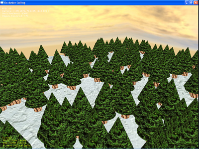
Diagram 5.1: Demo screenshot
Final Thoughts
Well, thank-you for checking out my implementation of occlusion culling. I hope that you gained some knowledge from it. I welcome any ideas, suggestions, or corrections.
Dustin Franklin
[email="dustinhimer@comcast.net"]dustinhimer@comcast.net[/email]
Dustin Franklin (aka circlesoft) is a high school student in Mount Joy, Pennsylvania. You can feel free to email him at [email="dustinhimer@comcast.net"]dustinhimer@comcast.net[/email] or contact him through MSN (at that address) or AIM (dutsin2323).