When you classify rendering techniques by the number of pixels they will impact in the final image. ShadowMapping is one of those features that have a non negligible effect on the overall realism of your scene.
But having a working shadowMap is one of the most trickiest problem I have found so far. In your journey across the shallow lands of depthExtraction you will find at least 4 different types of artifacts and each one of them is going to ruin your final rendering.
For each one you will encounter dozen of papers or so called shadow prophets which will sell you the undisputed truth but while implementing you will find border cases or maybe some of those techniques doesn't work with one another.
I am not here to sell you a new approach rather a complete working scenario for my special case of working in the CAO industry.
Overview
My special case is I have a highly detailed mesh with nothing in the background, and I want to be able to zoom in and actually show only a fine portion, actually one face. The light model used are parallel light rays close to a sun model. I only have one object, so a close range of available depth with little distortion effect due to perspective, with that in mind I don't have the need for cascade shadows and this example can be mapped in interior for video games.
Summary:
- Setting up the light point of view
- The perfect screenShot from light perspective
- Depth testing and application on the mesh
- Post-processing
- Stabilization
The final pipeline looks like this:
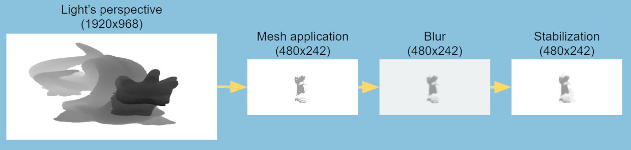
If you are an expert on the subject you are in common grounds, the new aspects you might discover are a first pass to compute the bounding volume of the scene and the use of temporal filtering to improve the shadow stabilization
Setting up the light point of view
Computing the view matrix of the light is trivial, but in our case the quantity of useful information we got from the shadowMap will come from the projection matrix, our goal is to fill the shadowMap with the maximum of pixels from our rendered objects using the camera perspective.
Typically this is done by finding a way to encompass the bounding volume of the light perspective with the one from the camera. What you have to do is to compute the world position of your camera frustum and try to find a ortho projection matrix that encompass it.
std::vector<vec4> ndcpoints = { vec4(-1, -1, -1, 1), vec4(-1, 1, -1, 1), vec4(1, -1, -1, 1), ... };
BoundingBox worldBbox;
for (auto& ndcPoint : ndcPoints) {
ndcPoint = toEye * ndcPoint;
ndcPoint = ndcPoint / ndcPoint.w;
auto currentWorld = toWorld * ndcPoint;
worldBbox.update(currentWorld.xyz());
}
BoundingBox lightBbox = worldBbox.transform(lightViewMatrix);
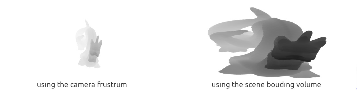
auto lightProjectionMatrix = glm::ortho<float>(-lightBbox.xLength() / 2, lightBbox.xLength() / 2, -lightBbox.yLength() / 2, lightBbox.yLength() / 2, near, updatedFar);This approach works well in open world games, when you have a high depth of field filled with useful informations, but in my case if I zoom out, my view frustum is much larger than the space occupied by my mesh and I lose lots of data.
In the end I added a first pass to compute the viewing volume, I parsed the depthbuffer of my scene on the cpu side. While parsing if one texel value is equal to the maximum depth range (value used for the initial clear) it should not be taken into account as part of the viewing volume, the resulting points will be used as the NDC limitation.
for (int j = 0; j < height; j++) {
   for (int i = 0; i < width; i++) {
       auto index = (j*width + i) * NB_CHANNELS;
       if (depth[k] != 1.0f) {
           if (DepthRenderingPass::minDepth > depth[k]) {
               DepthRenderingPass::minDepth = depth[k];
           }
           // ... same for maxDepth
           if (DepthRenderingPass::leftNDCBorder > i) {
               DepthRenderingPass::leftNDCBorder = i;
           }
           // ... same for rightBorder, bottomBorder, topBorder
       }
   }
}
The whole goal of tweaking the shadowMap is to produce a texture which maximize the space taken by the pixels from the cameraPerspective. Thanks to the bounding volume, I have the perfect ortho projection matrix with a very detailed near and far plane. This way my mesh occupies the maximum space on the shadowMap, if you have some perspective distortion, for example your light is looking in the reverse direction of your camera, you may take a look at perspective shadow map, in my case the light sits on top of the camera.
Depth testing and application on the mesh
You can increase the resolution of the light shadowmap to increase the precision of your depth test later on. Once you reach the camera space, you will have better performance. If you reduce the size of the shadowMap here are some advantages:
- - Post processing effects will be much stronger, resulting in a faster pass
- - Lesser use of the gpu memory, during the stabilization phase we store a duplicate for the next frame
- - One more blur from the linear filtering when accessing the texture for your final pass
When applying the shadow map to the mesh, you will face a wide range of artifacts, the most noticeable is shadow acnee
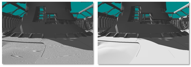
Once your understand the root cause of the problem you can call your self a shadowMap expert, this is my take on the subject. Shadow acnee can come from 2 differents source, the first one is your your attempt to map all the depth value in the [0:1] range, an infinite quantity, to a limited value stored in your depth format (typically a 24bit floating point value). This limitation can mapped different depth to the same value in your shadowMap.
Your depth value "z" will be mapped thanks to this formula:
\[ x = \dfrac{\dfrac{1}{z}-\dfrac{1}{near}}{\dfrac{1}{far}-\dfrac{1}{near}} \]
near = 1;
far = 1000;
F(700) = 0.99957, F(701) = 0.99948 ~= 0.9995;
Two different z are mapped to 0.9995. When you will finally compute the depth test, one of them will fail (700) cause we will compare the one stored in the shadowMap 0.9995 with the actal value 0.9957 and found that the actual fragment is occluded.
The other problem comes from a shadowMap being too small for your actual camera point of view.
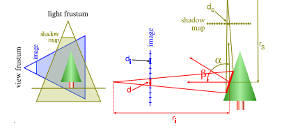
As you can see in this picture the side of the tree takes more space in the camera point of view than in the shadowMap. There are more pixels that covers the side of the tree in the screen than in the light point of view, hence some pixels you compute in the camera point of view will use the same depth information, some tests might point to the same shadow map pixel and will fail, see d > ds
The solution is to add a bias during the depth test, it can be seen as margin of error, with the bias you accept some tests that were rejected before. in the worst case scenario some pixels will be lighted instead of belonging to the shadow.
I use a constant bias with a "slope scale" bias:
float bias = 1.0 - clamp(dot(lightFragNormal, lightFragmentCoord), 0.0, 1.0);
bias = 0.002 + 0.002 * bias;
The less the face is turned toward the light, the greater the bias is increased. The constant values will depend on your scene don't take them for granted.
During this phase you could use the depth test on the neighboring pixels to soften your shadowMap, the common way is to use a technique called percentage closer filtering.
I use a uniform 3x3 radius, with no great improvement on the overall quality.
Post processing
These is where the magic append, the goal is to soften the final shadow to hide some unwanted artifacts and also to simulate soft shadows which are more appealing to the eye.
I used a 2 pass gaussian filter of size 13, equivalent of a one pass filter of size 23. The main performance of the algorithm came from this part, to speed up the blur pass I used:
- a common two pass filter, instead of doing a full pass with a kernel 13*13, I did one with a horizontal kernel 13x1 and another vertical one of size 1x13
- I discarded the last 2 values of each side of the kernel cause their values are meaningless
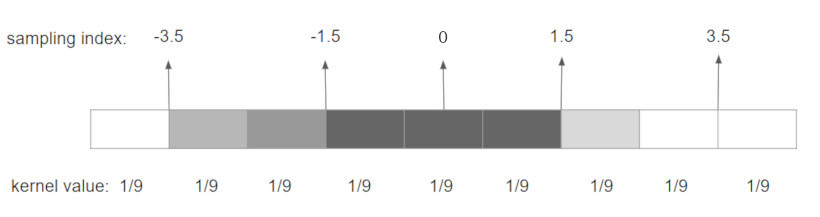
- I used linear filtering on the gpu side, instead of taking the center for each pixel, I filter 2 pixels at once by offsetting the sampling index with a weighted sum of the neighboring kernel values
I implemented a gaussian blur and a boxing blur, the boxing blur show more soften shadows and is easier to implement with all the offsetting process
For a boxing blur, you will sample at the mid point between 2 pixels, a naive algorithm would looks like this:
//Horizontal Boxing blur pass
for (int i = -4; i < 5; i=i+2) {
   float weight = i !=0 ? 2/9 : 1/9;
   vec4 result = texture(uv+offset, shadowMap) * weight;
}
Gaussian blur makes shadow harder, depending on the style of your application I would recommend you to still have a look to boxing blur
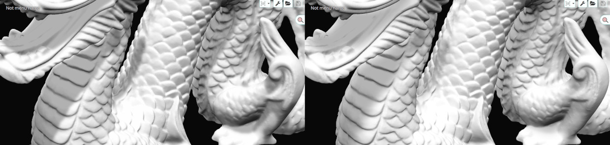
Stabilization
Stabilization artifacts appears when your light or a shadow caster move slightly. Like for example in a day/night circle or during the animation of your main character.
Those changes will trigger a new computation of the shadowMap with different values at the border of the shadowed areas. Those small differences between frames will trigger a unpleasant effect of shadow shimmering, flickering, aliasing or whatever you want to call it.
I have found some different approach on the internet but they mainly work for static geometry.
My approach was quite simple, I keep in memory the previous application of my shadow on the mesh, and I mix those previous result with the current ones.
For each frame I need to store the previous "shadow map" and the matrices used to compute the previous viewPoint.
vec4 mixShadow() {
   vec2 texture_coord = vec2(gl_FragCoord.x/viewPort.x, gl_FragCoord.y/viewPort.y);
   float current = Texture(shadowMap, texture_coord).r;

   vec4 previousFragPos = previousMVP * vec4(worldPosition, 1.0);
   previousFragPos = previousFragPos / previousFragPos.w;
   vec2 previous_texture_coord = (previousFragPos.xy + vec2(1.0, 1.0)) / 2.0;
   float previousShadow = Texture(previousShadowMap, previous_texture_coord).r;

   shadowFactor = abs(current + previousShadow) / 2.0;

   return vec4(shadowFactor, shadowFactor, shadowFactor, 1.0);
}
Link to the 2 videos:
If you end up reading those lines, it means I didn't kill you yet with technical details and confusing drawings.
I hope this work could help other people, if you have some comments like for example the fastest way to compute the actual viewing volume of the scene, feel free to ask.


Great work!