Making a curved model from 2 triangular models

Started by
7 comments, last by JoeJ 2 years, 2 months ago

Say you want to model a human head. Today you have a few options you could model the head with Nurbs or SubD which would be very inefficient for real time gaming and has some other modelling disadvantages, you could model the head with quads which also has some modelling disadvantages but is a lot quicker to render in real time or you could do what a lot of developers do and model it in triangles which once your talking enough triangles transformation and texture effects can look quite ok.

There is another way to model a head though. You could use two similar triangular models of your head and make one slightly bigger and one slightly smaller. Then you could render points between these two models. If you simply render the points half way between the two models you will get a new more advanced model but it won't be a truly curved model. In order to render a curved model from these 2 models you have to change the between point from 50% to 51% say relative to the furthest distance between the models back to 50% at the shortest distance. This will give you a curved model but you might want to tweak the ratio shifting to improve the output model.

Quite frankly this may or may not be that useful today in a world of high triangle counts and strong rendering of objects with unlimited triangle counts by reducing rendering of each frame. It certainly might help with reducing 3D data size for more curved objects. I wish I had discovered this technique 15 years ago when more curved looking models would have been more impressive.

Advertisement

qpwimblik said:
Today you have a few options you could model the head with Nurbs or SubD which would be very inefficient for real time gaming

That's not true. SubD models can be converted to simple triangle meshes on export, so no need to add any costs at realtime. That's how it's done almost always. Most characters are modeled with SubD, Nurbs are more interesting for technical models.
Some recent CoD had in engine SubD, and it was fast / advantageous for them, otherwise they would not have done it.
Implementing Catmull Clark on GPU is difficult, but possible. A visual advantage would be: You can skin the control mesh, then calculate the subdivision after that, which gives smoother and better skinning.

In order to render a curved model from these 2 models you have to change the between point from 50% to 51% say relative to the furthest distance between the models back to 50% at the shortest distance. This will give you a curved model but you might want to tweak the ratio shifting to improve the output model.

I doubt this gives curved models. An average of two planar triangles more likely gives just another plane. So you eventually can capture the detail of both models, but it would not smooth it out further, and you still get planar sections in regions where none of the two meshes has vertices or edges?
You could show us some images of your technique, but i'm sure SubD modeling remains the easier and better solution in general.
However, SubD modeling (usually based on Catmull Clark), requires experience on dealing with singularities (vertices with a number of adjacent edges different than 4, or polygons with an edge count different than 4). That's a downside, but once learned it becomes intuitive and flexible to work with, and gives high quality results. (Mastering Nurbs is much harder, while polygon modeling is easier but unpractical for organic / curved surfaces)

qpwimblik said:
I wish I had discovered this technique 15 years ago when more curved looking models would have been more impressive.
The reason to use low poly models was not the difficulty to create them, but the performance cost to render them.

qpwimblik said:
you could model the head with quads which also has some modelling disadvantages but is a lot quicker to render in real time

That's not true either.
Quads are always converted to two triangles by GPU drivers, and recent APIs even removed to support quads but require triangles, so you have to do the conversation on your own.

fleabay said:
If only there was a way to store the points of the new model's spacial differences in a texture and somehow superimpose that texture over the lower poly model, to simulate curves and more detail. It would become the Normal way to do things.

Sounds you want displacement mapping? It can not add new topological features like holes, but you can store the detail in textures and use mip maps for dynamic LOD. And with 3D vector displacement over just 1D height, it's a lot of potential.

The reason i think it did not became a game changer is texture seams. Standard UV mapping generates islands of UV charts, and at their boundary the texels do not precisely match to adjacent texels, so you get cracks in the displaced surface. In practice, this restricts displacement mapping to limited use like terrain.

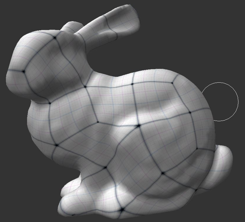
There is however a way to avoid texture seams. It requires to solve the difficult problem of quadrangulation. I worked on this:

With such UVs, i could displace the bunny using pot textures without any cracks over a low poly quad mesh, and add detail with little cost. Displaced edge flow aligns to principal directions of curvature, so mesh quality would be good as well. (Some constraints on matching adjacent texels to be equal are needed to support filtering, which is easy.)
But it's still restricted. If the bunny had smaller features, like much smaller ears, i'd need to use smaller quads everywhere to capture the ears topology.
Or i could ignore the ears and express them only with displacement. This would work but with heavy UV distortion, so geomteric quality of ears would suffer.

Surely interesting if we aim for high detail and good compression, but it can't do everything. Nanite for example is much more flexible.

"I doubt this gives curved models. An average of two planar triangles more likely gives just another plane"

Um if you have 2 straight line equations intersecting and another line equation at the intersection point that is half way between the two other lines and then you shift the ratio. in shifting the ratio you get a curve not a straight line.

Technically it can't be straight if you shift the ratio smoothly because doing this is equivalent to bending the line.

My curved model idea uses the same principle in 3D.

The 2D example of the principle isn't that hard to formulate on a graphing package.

@fleabay You can calculate voxels between the two triangular models and give each voxel colour relative to the two very similar textures on the triangles the issue might also enable some enhancements to voxel transformation effects.

qpwimblik said:
Um if you have 2 straight line equations intersecting and another line equation at the intersection point that is half way between the two other lines and then you shift the ratio. in shifting the ratio you get a curve not a straight line.

Ah ok. That's what you meant with variable percentages - i was confused by that.
Though, then you have the usual problem of finding such ratio value to ensure something like C2 continuity, which is important to prevent artifacts if tessellation becomes high. It becomes very visible with specular lighting.
Catmull Clark isn't perfect in this sense either - you want to place your singularities at pretty planar parts of the surface to hide the issues. Nurbs is better formulated, but just too complicated to allow an artist friendly, organic workflow.

The perfect surface representation for intuitive modeling has not been found yet.
I had one idea which is similar to yours: Use patches where we can model curvature using few control points as usual, but there should be no need to join all patches to form a connected surface.
Instead the patches could overlap, and the application finds an average surface from multiple, disconnected patches, e.g. by giving the patches a low weight near their boundary, but high weight on their interior.
Then, some remeshing algorithm can turn the average surface into a final mesh.
We would have little control over individual triangles, but the burden of dealing with singularities, and the frustration of resulting compromises on edge flow would go away.

It's somewhere on my todo list, but i'm surely long dead until i get to this point :D

@JoeJ I think the issue is C0 continuity if you are for example shifting the ratio relative to the furthest distance apart and the shortest distance apart between the 2 models essentially because the ratio loop is in this case is so bound to the foundations of the model you end up with C0 continuity. If the curve ratio needs tweaking at a more local level of the model then you would have to line up with all edges and intersections of an equivalent non curved reduced model to error correct the ratio shift solving the alignment problem such a trick would not work so well with other curved modelling types where you can't get round the issue so easily by simply lining up lines as Nurbs are not so forgiving and DSub still a work in progress.

Good luck with your algorithm.

qpwimblik said:
I think the issue is C0 continuity if you are for example shifting the ratio relative to the furthest distance apart and the shortest distance apart between the 2 models essentially because the ratio loop is in this case is so bound to the foundations of the model you end up with C0 continuity. If the curve ratio needs tweaking at a more local level of the model then you would have to line up with all edges and intersections of an equivalent non curved reduced model to error correct the ratio shift solving the alignment problem such a trick would not work so well with other curved modelling types where you can't get round the issue so easily by simply lining up lines as Nurbs are not so forgiving and DSub still a work in progress.

Wow. Your sentences are even longer than mine. I fail to parse the grammar! :D
But thinking about your idea again, we could make a 2D example for simplicity:
A low poly mesh on the plane, with random interior vertices, connected by edges forming a nice Delauney Triangulation.
And a second mesh on top, also planar and Delauney, but eventually more vertices at higher density.
Then, we could merge the two, which would be as simple as taking all vertices from both, project them to the same plane, and make a new Delauney Triangluation from that.
The initial edge flow would be lost, but lets ignore this, because we do not really want to care about edge flow at all. That's just some artificial constraint computers impose to us, and as artists we do not really want this. Dealing with discrete vertices is pain enough.
The problem at this point would be that we have many sliver triangles, where one edge is almost as long as the sum of the other two, and we have two small angles.
In such regions there is no way to avoid artifacts. If we bend the mesh, it won't look smooth, even if we guarantee C2 continuous curvature across edges with our subdivison or parametric patches.
The only way to avoid the issues would be to make sure the combination of our initial meshes doesn't generate such bad triangles. Either by trying to keep vertices at some distance from each other, or by making sure they merge to a single one.

I think that's the kind of problem you will encounter.
Thus i ask: Wouldn't it be easier to model just one mesh instead two? Because this way we do not need to predict the outcome of a merging process. We already can see all the issues instantly, while working on it.
Ofc. the computer could help the modeler, e.g. by relaxing the merged mesh so triangles become more regular, or by resampling the surface and remeshing it nicely. But this will always work against the artists intend in some cases.

Still, let us know about your outcome. I'm curious… : )

This topic is closed to new replies.

Advertisement