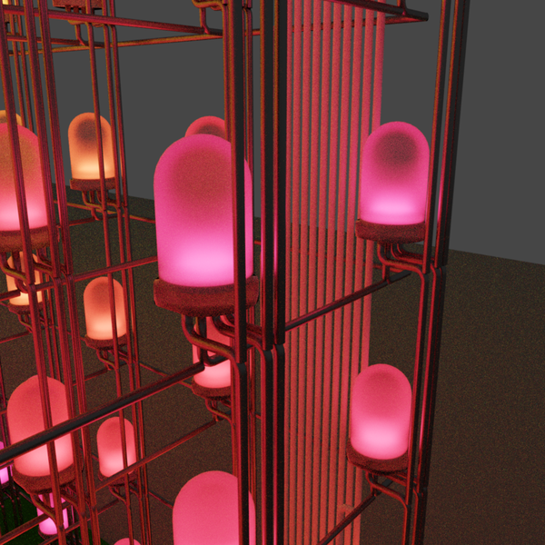
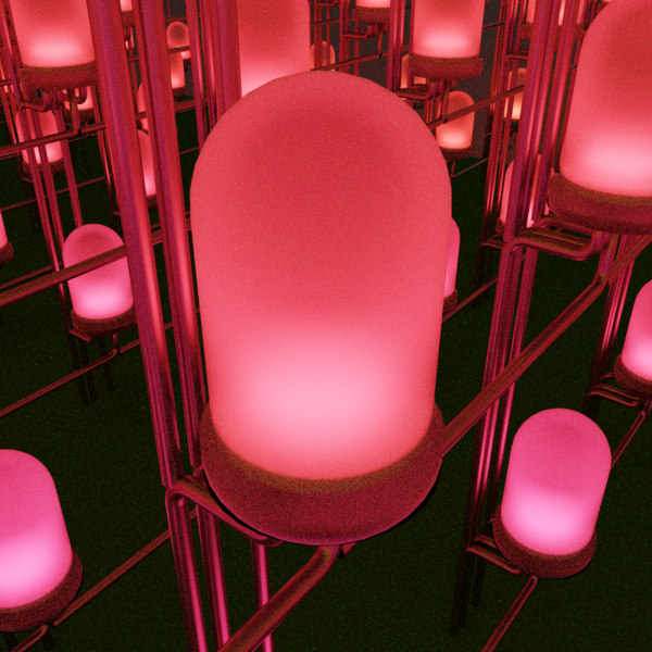
One thought you might have when hearing "LED Cube" is: What use are the LEDs in the center? Are they even visible, or are they covered up by all of the other LEDs surrounding it?
They are. That's why it's preferable to choose LEDs with small housings and space them as far apart as possible. The "empty space to LED ratio" needs to be as large as possible.
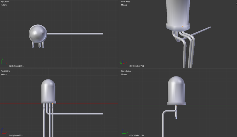
After searching multiple LED suppliers, I found that the smallest viable RGB LED is 5mm in diameter, with pin lengths of 25mm. To get an idea of what the cube might look like and also to figure out how the LEDs should be connected to one another, I decided to model the LED in blender. I came up with the following layout.
It would be impractical to address all LEDs simultaneously. This would mean having 4096*3 control signals! I figured that the highest number of LEDs I would dare control simultaneously would be 768, which happens to be the exact number of LEDs in a single "slice" of the cube. In order to control all 16 slices, we use multiplexing: That is, we need to cycle through each slice repeatedly and apply the 768 signals for the active slice. If you do this fast enough, the human eye will think all of the LEDs are turned on.
Knowing that ICs generally are able to sink higher currents than they are able to source currents, it is preferrable to use a common anode LED and connect all anodes in a cube slice together, making it possible to switch slices of the cube on and off with power transistors. The anode is the connection branching off to the right in the picture above.
The 3 cathodes for controlling the red, green and blue LEDs in the housing are branched off downwards.
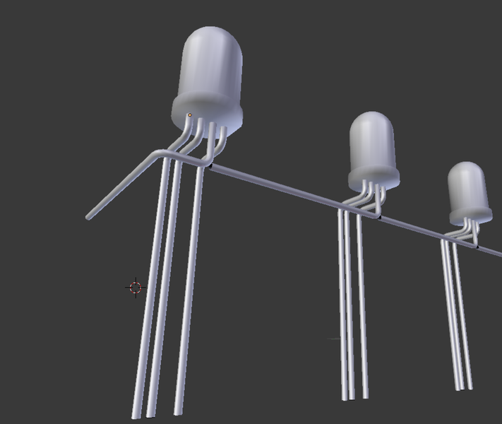
The idea here is to chain the LEDs together such that the anodes can be soldered together like so:
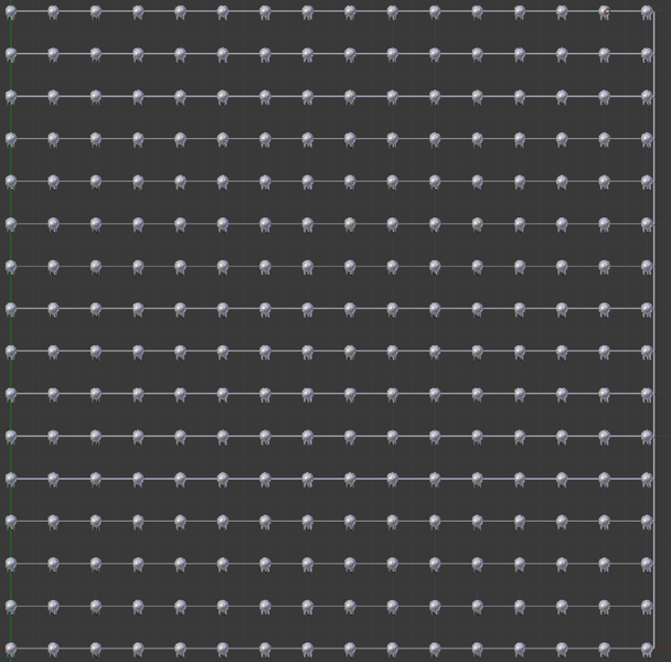
And by soldering these strings into an array, we get a single slice of the cube with all anodes connected to the same net:
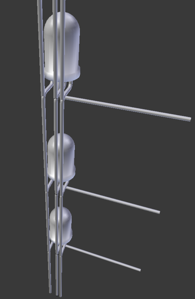
16 of these slices are then stacked on top of each other such that the cathodes align perfectly with the underlying layer and can be soldered together:
The result is a structure that looks like this (using 4x4x4 here for clarity, things get messy to look at with 16x16x16):
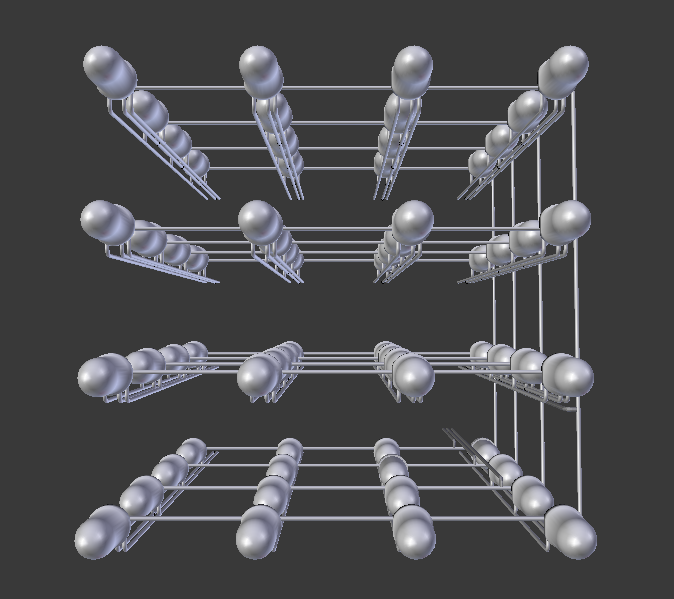
The 768 + 16 pins that end up sticking out of the bottom of this structure will be soldered onto a PCB. The number of signals can further be decreased by using shift registers (most likely I'll be using 32x 24-bit shift registers which will decrease the 768 signals to 32. This, an FPGA can handle).
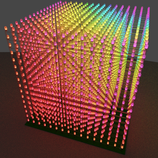
To finish things off, since this is blender, I rendered some pictures of how the cube might look in the end. Enjoy!


