GameDev.net gamedev.net
🔒 Locked

Clutch Modelling Help

Started by Vu Chi Thien Jan 26, 2018 at 5:42 PM 17 replies 18.5k views
Original Post
Vu Chi Thien
Vu Chi Thien

Hi fellow game devs,


I'm working on a car simulator using Unity3D and currently stuck on implementing the clutch.

Currently, my drivetrain model involves torque from engine and reaction torque from the drivetrain and is using Unity3D wheelCollider. My ultimate goal is to calculate engineRPM at each time step, from there lookup engineTorque from torque curve and send to the wheels through drivetrain. Known variables are wheelRPM (reported from wheelCollider, read only), wheelInertia (calculated from wheelMass and radius, reported from wheelCollider), and engineTorque from a torque curve. Right now for simplicity, I'm ignoring drivetrain inertia and the differential is open.

This is my currently non-working procedure, I'm using the formula AngularAcceleration = Torque/Inertia, so each timestep engineVelocity += AngularAcceleration.

wheelAngularMomentum is calculated using Momentum = Inertia * AngularVelocity. Take the sum angular momentum of all the driven wheels, convert that angular sum to torque by divide torque to detalTime, because deltaMomentum= Torque * deltaTime, so Torque = deltaMomentum / deltaTime (I don't know if I'm right or not here). This torque will be wheelReactionTorque.

For engineCombustionTorque, I use a curve to look up torque at certain RPM. Then engineTotalTorque will be engineCombustionTorque - frictionTorque. This sum of torque is the torque at the engine acting on the flywheel.

engineTotalTorque then drives the flywheel with its inertia engineInertia. This engineTotalTorque is resisted by the above wheelReactionTorque. So the netTorque is engineTotalTorque - wheelReactionTorque. This netTorque still drive only the flywheel which is engineInertia, but is resisted by the reaction torque from the wheels. So now the engineRPM is calculated using the formula AngularAcceleration = Torque/Inertia this way: engineRPM += netTorque / engineInertia * deltaTime.

The biggest problem now is I don't know which force/torque will be transfered to the wheel and drives the wheels. Can you please help me out here?

Second, I don't know where and how to put the clutch in-between, I'm thinking of have a clutchInput float in wheelReactionTorque, so when it's 0 ie clutch disengaged, no resistance torque, engine freely spin the flywheel. clutchInput > 0, percentage of resistance is there, engine now drives itself and the resistance. What do you think about this?

Third, should the wheelResistanceTorque be modified with gearRatio before going back to the engine, say wheelResistanceTorque / gearRatio, or wheelResistanceTorque * gearRatio? If yes, should it be divide or multiply? I know that engineTorque going to wheel will have to be multiply with gearRatio, but what about the torque from wheel going back looking from the engine side?

I'm planning to stick with built-in wheelCollider despite its drawbacks to save time. I would like to make some sort of "sim-cade" handling similar to GRID or TDU, where the physic and handling is arcade-y, but still involves real physic factors such as managing clutch, tuning suspension, etc, as oppose to fully arcade games like need for speed or burnout.

Thank you guys very much in advance.

CombatWombat
CombatWombat

Well. It's been a while since I've done this stuff, but let me see if I can help.

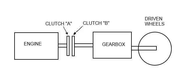
Let us refer to this diagram.

DRIVETRAIN.png.580959f38254cf6846798371cc45b804.png


Engine will look like:


torqueProduced = throttle * torqueLookup(RPM);	// throttle 0.0f - 1.0f
frictionTorque = frictionTorqueLookup(RPM);		// could be a constant value or linear to RPM.  You need to experiment
engineNetTorque = torqueProduced + clutchReactionTorque - frictionTorque;
engineAngularAcceleration = engineNetTorque/engineInerta;


Gearbox will look something like:


outputShaftSpeed = drivenWheelRPM;	// Let's ignore the differential gearratio and bake it into the gearbox overall ratio.
inputShaftSpeed = outputShaftSpeed * currentGearRatio;	// Lookup based on current gear selection.
outputTorque = clutchReactionTorque * currentGearRatio;


Driven wheels:


netTorque = reactionTorqueFromGround + (gearboxOutputTorque / numDriveWheels);
angularAcceleration = netTorque/wheelInertia;


Now the bit to put it all together... The clutch.


clutchASpeed = engineRPM;
clutchBSpeed = gearboxInputShaftSpeed;

// Now, when the clutch is engaged, it wants its two speeds to be equal.
// So it should apply reaction torques to try to achieve this. 
// A naive approach might look something like:
clutchTorque = frictionConstant * clutchFactor;  // clutchFactor = 0.0f -> 1.0f
if(clutchASpeed > clutchBSpeed)					 
	reactionTorqueA = -clutchTorque;
	reactionTorqueB = clutchTorque;
else
 	reactionTorqueA = clutchTorque;
	reactionTorqueB = -clutchTorque;
// This may have problems where is oscillates around equal speeds.  
// Depends on your integrator timestep, masses, etc.
// You could experiment with making the reaction torque linear to slip speed, 
// putting limits as the speeds get close to equal, etc.

So, what should happen, is when the engine is faster than the input shaft of the gearbox, the clutch generates a torque that tries to slow the engine and tries to speed up the gearbox. Vice-versa when the engine is slower than the gearbox input. The gearbox multiplies this torque and sends it to the wheels. (Divide it up by the number of drive wheels).

As I said, it's been a long time since I've done this. So I could have missed something somewhere, but a similar approach has worked for me in the past.


Vu Chi Thien
Vu Chi Thien

Oh boy, what a warm welcome for a complete beginner like me. Looking at your implementation I just want to punch myself, because of how obvious and easy it is, and I'm here digging myself in all of the complicating maths.

However I'm still confused in some places:

15 hours ago, CombatWombat said:

engineNetTorque = torqueProduced + clutchReactionTorque - frictionTorque;

I'm guessing this clutchReactionTorque is reactionTorqueA? Because when engine is faster than wheels, engine must be slowed down like this:

15 hours ago, CombatWombat said:

if(clutchASpeed > clutchBSpeed) reactionTorqueA = -clutchTorque;

Next is the gearBox:

15 hours ago, CombatWombat said:

outputTorque = clutchReactionTorque * currentGearRatio;

I thought the output of the gearbox should be what ever the engine is outputing through clutch * gearRatio? If the output torque is clutchReactionTorque, in this case I'm guessing reactionTorqueB. then the torque at the wheels will be very very small, because in this reactionTorqueB is just clutchTorque, which is clutchFactor * frictionCoefficient.

15 hours ago, CombatWombat said:

reactionTorqueB = clutchTorque;

Or maybe I guessing you meant


clutchNetTorque = engineOutputTorque - reactionTorqueB;

then this clutchNetTorque will be driving the gearbox, and then the gearbox torque now drives the wheels?


So in my mind the model looks like this:


engineNetTorque = engineTorque - frictionTorque + reactionTorqueA;

clutchNetTorque = engineNetTorque + reactionTorqueB;

gearBoxOutTorque = clutchNetTorque * gearRatio;

wheelTorque = gearBoxOutTorque * diffBiasRatio; //use torque because Unity's wheelCollider RPM is read-only

By doing this, both sideA (engine) and sideB (shaftIn) will be dependent on the reactionTorque at the clutch, and both sides will rotate freely, connected only by the clutch. shaftIn torque will affect both engine the engine and the wheels

Then the cases for reactionTorque;


if (sideA > sideB) //engine (sideA) is faster, brake engine, speed up shaft (sideB)
{
  reactionTorqueA = -clutchTorque;
  reactionTorqueB = clutchTorque;
}
else if (sideA < sideB) //shaft is faster, brake shaft, speed up engine
{
  reactionTorqueA = clutchTorque;
  reactionTorqueB = -clutchTorque;
}
else //equal speed, reactionTorque is 0
{
  reactionTorqueA = reactionTorqueB = 0;
}
  

Also I'm thinking about making reactiontorque = (sideA - sideB) * clutchfactor, that way the if statement can be omitted and only the applying the correct sign at sideA and sideB is needed.

Any opinions on the above?


Also kind of out-of-place but I also would like to ask about differential after the clutch model is done, is it OK?

Vu Chi Thien
Vu Chi Thien

Update: I sort of having a rough implementation of this, and my problem now is that the engine keeps on accelerating like there is no resistance torque from the clutch, and the output torque at wheel is tiny.

Here is my code so far, I'm using (engineSpeed - wheelSpeed) for reaction torque, so that I can omit the if statements:


//speed is in rad/s
//torque in Nm
//inertia in kg/m^2
//clutchStrength is abitrary, currently 10
//clutchInput goes from 0 (depressed, engaged) to 1 (pressed, disengaged)
float clutchTorque = (engineSpeed - driveTrainSpeed) * (1.0f - clutchInput) * clutchStrength * gearClutch; //gear clutch is when in neutral gear which is ratio 0

float engineOutputTorque = currentTotalEngineTorque - clutchTorque; //the torque coming out of the engine, factored in friction and resistance from clutch
float clutchOutputTorque = (engineOutputTorque + clutchTorque) * (1.0f - clutchInput); //the torque coming out of the clutch to drive the gearBox, the problem is somewhere here I guess. 1.0f-clutchinput is added later because torque is able the reach wheels even if clutch is disengaged, maybe problem related to this also.
float outputTorque = clutchOutputTorque * currentGearRatio * finalDriveRear; //the torque coming out of the gearbox to drive the wheels

 currentEngineRPM += radsToRPM((engineOutputTorque * Time.fixedDeltaTime) / engineInertia) ; //accelerate the engine with the netTorque

//finally drives the wheels
RR.motorTorque = outputTorque / 2.0f;
RL.motorTorque = outputTorque / 2.0f;

So the problem maybe is that clutchTorque that resists engine is too low so the engine keeps on accelerating like there's no resistance at all. When shifting gear the engineSpeed doesn't jump back either.

Also the input torque for clutch maybe is wrong. I'm specifying the net engine output torque as input, which maybe is wrong because only fraction of the engine output torque should be in the clutch when clutch is slipping. Or maybe the output altogether is wrong (which is engineOutputTorque + clutchTorque).

Can someone take a look and give me some advice?

Thank you very very much.

bmarci
bmarci

Hi, Just a quick addition. It seems you already experienced something related.

The engine/gearbox speed will never be the same, so some torque is always applied and with small difference it'll overshoot the acceleration, and develops some vibration, and that could go wrong.

So when I made mine, I had an open-locked clutch state.
Open by default until the engine and gearbox "equal" speed, in practice, when the sign of the speed difference changes.

So when locked, you don't need to add clutch torques any more, just apply the engine torque directly to the wheels like the whole thing was fixed together.

And most importantly there should be a setting for the maximum clutch torque, that's the amount the clutch can deal with (this should be multiplied by the current clutch pedal position). If the engine or wheel reaction torque is greater than this the clutch starts slipping and gets open again, so you can apply those clutch torques again.

I hope I could give some hint:)


Vu Chi Thien
Vu Chi Thien
1 hour ago, bmarci said:

Hi, Just a quick addition. It seems you already experienced something related.

The engine/gearbox speed will never be the same, so some torque is always applied and with small difference it'll overshoot the acceleration, and develops some vibration, and that could go wrong.

So when I made mine, I had an open-locked clutch state.
Open by default until the engine and gearbox "equal" speed, in practice, when the sign of the speed difference changes.

So when locked, you don't need to add clutch torques any more, just apply the engine torque directly to the wheels like the whole thing was fixed together.

And most importantly there should be a setting for the maximum clutch torque, that's the amount the clutch can deal with (this should be multiplied by the current clutch pedal position). If the engine or wheel reaction torque is greater than this the clutch starts slipping and gets open again, so you can apply those clutch torques again.

I hope I could give some hint:)


Hi.

Thank you so much for your reply. Yes you gave me some precious light when I'm in total darkness like right now.

Actually my model I'm thinking of doing right now is very similar to what you've said, having a clutch with states. Before this I've looked this model from Matlab:

https://www.mathworks.com/help/simulink/examples/building-a-clutch-lock-up-model.html

It's a very clean implementation, but doesn't fit Unity3D's physic engine too well, so I have to modify it and ended up with the model posted above. I'm thinking of making the clutch as a separate C# class, integrate as a separate object and output appropriate torque to engine and wheel side. The stuff I posted here is what I'm testing with the case of slipping clutch.

In case of locked clutch, I'm thinking of just setting the engineSpeed to the wheelSpeed * gearRatio, and engineTorque * gearRatio goes straight to the wheel. To me it's easier since Unity3D's physic engine calculate the wheelSpeed of the wheel object (wheelCollider) for me based on how much torque I put in and the tire slip force setting. Also this is the "recommended way" of doing engineSpeed according to Unity, which I think is not the best.

The hard thing is the slipping clutch. The downside of Unity's physic engine is that it does not expose the rolling resistance force and load of the wheel, so having wheel resistance torque acting back on the engine is not possible. The only way is to use wheelSpeed.

However, it's possible to calculate the angular Momentum of the wheel because the physic engine exposes wheel radius, weight and speed. So is it possible to somehow convert the momentum of the wheel to torque and resist the engine?

Also would you mind explaining this:

2 hours ago, bmarci said:

Open by default until the engine and gearbox "equal" speed, in practice, when the sign of the speed difference changes.

What do you mean by sign changed? Is it like

if sign(speedBefore) != sign(speedAfter) then clutchLocked

So based on what you've said, I have this model in mind


bool clutchLocked = false; //clutch open by default
float engineTorque = lookUpCurve(engineSpeed) - friction - clutchResist; 
//find out if clutch is slipping
//if engine torque overcomes clutch avaiable torque
//or speed different higher than threshold (since can't use wheel resistance torque for now)
if (engineTorque > clutchTorque || Abs(engineSpeed - wheelSpeed) > threshold)
{
  clutchLocked = false;
}
else 
  clutchLocked = true;


if (clutchLocked) 
{
  engineSpeed = shaftSpeed; //when clutch locked engine speed == wheel speed over gear system
  //all available engine torque goes to the wheels
  clutchResist = 0;
}
else  
{
  //clutch slipping
  //engine torque drive the engine itself with resistance from clutch
  //not going dirrectly to wheels
  engineSpeed += engineTorque / engineInertia * deltaTime;
  clutchResist = (engineSpeed - shaftSpeed) * clutchInput * clutchStrength;
}

Of the locking check can be like this (according to how I understand what you've said):


float speedDiff = engineSpeed = shaftSpeed;
//when sign changes or torque at both side less than clutch torque, clutch is locked
if ( sign(speedDiff) != sign(engineSpeed - shaftSpeed) || (engineTorque < clutchTorque && wheelTorque < clutchTorque) ) 
{
  clutchLocked = true;
}
else 
  clutchLocked = false;

What do you think? Would you mind giving me advises?

CombatWombat
CombatWombat


Your implementation looks close, but let's put some numbers and see where it's going awry.


// Let's pick some reasonable starting conditions for trying to accelerate.
// EngineRPM: 1000	[104.72 rad/s]
// DrivelineRPM: 0	[0 rad/s]
// EngineTorque(1000) = 400 Nm
// 1st Gear Ratio: 3.00
// Final Drive Ratio: 3.73


float clutchTorque = (engineSpeed - driveTrainSpeed) * (1.0f - clutchInput) * clutchStrength * gearClutch;
// (104.72 - 0) * (1.0f - 0.0f) * 10.0f * 1.0f = 1047.2 Nm
// This is a lot of torque and should definitely accelerate something!
// I would lean towards calling this "clutchReactionTorque" or something similar.  
// It is the torque acting between the two discs.


float engineOutputTorque = currentTotalEngineTorque - clutchTorque; 
// We're saying engine is making 400Nm, so 400Nm - 1047.2Nm = -647.2Nm.
// I would call it "engineNetTorque".  We're not actually "outputting" it anywhere.


float clutchOutputTorque = (engineOutputTorque + clutchTorque) * (1.0f - clutchInput);
// I don't understand this, really.  I think it might be where the problem is, but let's try anyways...
// (400Nm + 1047.2Nm) * (1.0f - 0.0f) = 1447.2 Nm.
// I think correct line would be clutchOutputTorque = clutchTorque;  
// This is because if you draw FBD of the clutch output plate, it only 
// knows about clutch input plate and gearbox.  It has no idea what engine is actually doing.  
// It only knows that clutch input plate is rubbing against it with some friction force.

float outputTorque = clutchOutputTorque * currentGearRatio * finalDriveRear;
// 1447.2Nm * 3.0 * 3.73 = 16194.17 Nm.  This is a big number of torques.  So something should drive somewhere.

 currentEngineRPM += radsToRPM((engineOutputTorque * Time.fixedDeltaTime) / engineInertia);
// so, we saw that engineOutputTorque is actually -647.2Nm, so the engine should slow down.

//finally drives the wheels
RR.motorTorque = outputTorque / 2.0f;
RL.motorTorque = outputTorque / 2.0f;
// Each wheel receives 8097.09 Nm.  So assuming the sign is correct (positive number rotates so the car goes forward), 
// then wheel speed should increase.  Drivelinespeed should increase.  Enginespeed will decrease as we saw above.  
// This brings clutch plate speeds closer together. So things appear to be close to working.  
// Try outputting debug numbers and see if things are behaving as above.


What was said above about switching to a "locked clutch" model when speeds equalize is a good idea, but it shouldnt be necessary to get things driving presuming your integrator is stable enough that things don't completely explode.

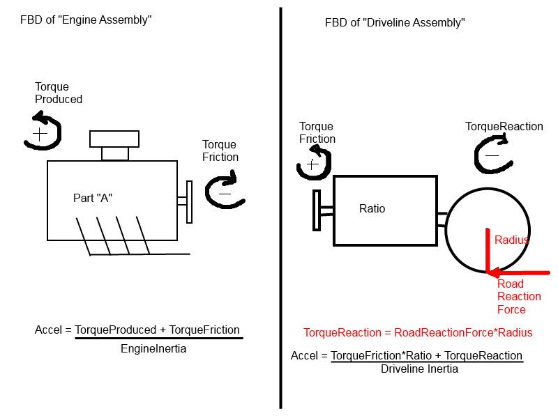
Edit: I would like to clarify that for the model as shown, the clutch and gearbox are both kinda of "virtual". We have not assigned mass or inertia to them. In a way they are just typedefs or "specially named attachment points" of the engine and wheel, since those are the only things with mass in the system.

Specifically, the "A" side of the clutch will always have the same speed as the engine. It is effectively part of the engine, but we give it a special name for convenience.

Same with the "B" side of the clutch, the gearbox, and the wheels being one "unit".

See the following, because MSPaint is THE tool of the future:

FreeBodyDiagram


FBD.png.6ea0a1a0359a6f4d0cd3eca5dec52db1.png

Vu Chi Thien
Vu Chi Thien

Thanks for the awesome reply.


clutchTorque = (engineSpeed - driveTrainSpeed) * (1.0f - clutchInput) * clutchStrength * gearClutch;
17 hours ago, CombatWombat said:

Specifically, the "A" side of the clutch will always have the same speed as the engine. It is effectively part of the engine, but we give it a special name for convenience.

Same with the "B" side of the clutch, the gearbox, and the wheels being one "unit".

Oh OK I understand now. So basically I can imagine this as the engine driving the gearbox directly, but the two can be taken apart to spin independently.

17 hours ago, CombatWombat said:

// I think correct line would be clutchOutputTorque = clutchTorque; // This is because if you draw FBD of the clutch output plate, it only // knows about clutch input plate and gearbox. It has no idea what engine is actually doing. // It only knows that clutch input plate is rubbing against it with some friction force.

This is where I lost it. So based on the model of clutchTorque


clutchTorque = (engineSpeed - driveTrainSpeed) * (1.0f - clutchInput) * clutchStrength * gearClutch;

if this clutchTorque is used to drive the wheels, then there will be torque only if there is different in engineSpeed and wheelSpeed, ie torque is highest if clutch is slipping like crazy, which is not correct. And since this torque is fed back to the engine, then the engine speed would going up and down in a unrealistic manner.

Another thing is that the engine torque does not go to the wheels but only the reaction torque does, which is

On 1/28/2018 at 4:37 AM, CombatWombat said:

clutchTorque = frictionConstant * clutchFactor;

which is a very small amount of torque.

Looking at the diagram (which is the best by the way), the way I understand it is that the engineNetTorque drives the flywheel, which is sideA. A fraction (0 - 100%) of that torque must affect/output to sideB, and how much of engineNetTorque is going to sideB depends on the amount of space in between sideA and sideB.

Or actually a fraction of combustionTorque (not netTorque) is going to sideB and the amount depends on the space in betweeen. The same with reaction torque on engine, the amount of that reactionTorque depends on the space as well.


This is the biggest confusion in all the clutch model I've looked at. Would you mind explaining a little bit more on this? Also one thing to note is that in the current physic engine I'm using (Unity3D), there is no way to extract roadReactionTorque at the wheel to feed back on the engine, so wheelReactionTorque = roadTorque + torque friction is a no go (well if that's the only way and its necessary in this model). That's why I'm replacing the whole wheelReactionTorque with the above (engineSpeed - wheelSpeed).

Second is that it is not possible to manually modify rpm, so wheelRPM += wheelAcceleration is a no go either. The way it works is that I give the wheel a torque value and the engine would integrate and return the rpm and slip based on the slip tire force curve (Pajeka like curve).

However it is possible to get angular momentum of the wheels since wheel mass, radius and rpm are exposed. So is there any way to extract torque from angular momentum (or impulse) to apply to the roadTorque + torqueFriction model?

Vu Chi Thien
Vu Chi Thien

Here is the debug log in a run at 1st gear and specs of the car:


//In 1st gear launching
EngineSpeed: 19.20 DrivetrainSpeed: 0.00 clutchTorque: 253.54 engineTorque: 63.55 engineOutput: -189.99 clutchOutput: 31.08 output: 485.07
//Accelerating
EngineSpeed: 19.07 DrivetrainSpeed: 0.02 clutchTorque: 251.42 engineTorque: 100.46 engineOutput: -150.96 clutchOutput: 49.13 output: 766.80
EngineSpeed: 18.96 DrivetrainSpeed: 0.05 clutchTorque: 249.57 engineTorque: 128.12 engineOutput: -121.46 clutchOutput: 62.65 output: 977.87
//So the RPM did jump down until the engine output torque ie net torque is  positive
EngineSpeed: 16.43 DrivetrainSpeed: 10.16 clutchTorque: 169.31 engineTorque: 200.51 engineOutput: 31.20 clutchOutput: 200.51 output: 3129.79
EngineSpeed: 16.46 DrivetrainSpeed: 11.47 clutchTorque: 134.66 engineTorque: 200.55 engineOutput: 65.90 clutchOutput: 200.55 output: 3130.44
//HOwever eventually the engineRPM reach Max, but wheel RPM doesn't match, thus output torque is tiny.
//Also the rev limiter kicked in making engineTorque 0, making the engine the same speed but wheel speed also never match
//and the final output torque can't accelerate the wheels anymore.
EngineSpeed: 19.46 DrivetrainSpeed: 19.27 clutchTorque: 5.38 engineTorque: 5.38 engineOutput: 0.01 clutchOutput: 5.38 output: 84.01
EngineSpeed: 18.20 DrivetrainSpeed: 15.34 clutchTorque: 77.11 engineTorque: -118.47 engineOutput: -195.58 clutchOutput: -118.47 output: -1849.13

Subaru BRZ:

1st gear: 3.63

Final drive: 4.3

I actually had wheelspin when launching, but after that, the engineRPM accelerated way ahead of the wheelRPM though clutch fully engaged, and engineRPM kept staying at max, and wheelRPM slowly caught up after, which is not real. So it's a chase between the wheelRPM and the engineRPM. It's like the clutch was too weak. But increasing clutchStrength would cause haywire due to large number. I will post a video later to demonstrate.

Vu Chi Thien
Vu Chi Thien

Here is the demo video. Sorry for the buggy audio since I'm debugging a lot and there's little to no optimization at this moment.

As you can see (and hear) the engine revs up to max while the wheel rpm keeps up. The Delta W in the inspector window on the right is (engineRPM - wheelRPM), and you can see that they never match, and wheelRPM tried to keep up very slowly. No matter how high the clutch strength value is, they never match. The clutch strength value now is 27.

Unity 5.6.1f1 Personal (64bit) - DevelopmentTestTrack.unity - Car0 - PC, Mac & Linux Standalone _DX11_ 31-Jan-18 1_06_39 AMTrim.mp4


CombatWombat
CombatWombat
Quote

if this clutchTorque is used to drive the wheels, then there will be torque only if there is different in engineSpeed and wheelSpeed, ie torque is highest if clutch is slipping like crazy, which is not correct. And since this torque is fed back to the engine, then the engine speed would going up and down in a unrealistic manner.

Using that linear model you are simulating something closer to a torque converter (fluid coupling used in automatic transmissions) rather than a clutch. So that's why there's lots of slipping.

This can be ok, maybe you just need "stiffer" constants:


clutchTorque = 50.0f * (engineRPM - drivelineRPM)...
//or
clutchTorque = (engineRPM - drivelineRPM)^2 ...
//etc

Or if you just do:


if(engineSpeed > drivelineSpeed)
  clutchTorque = blah;
else
  clutchTorque = -blah;

Then you will have lots of torque as soon as you have 0.00001 slip. You might need a combination of the two to get enough clutch "grab" but not have an unstable simulation.


Quote

Another thing is that the engine torque does not go to the wheels but only the reaction torque does, which is

On 1/27/2018 at 4:37 PM, CombatWombat said:

clutchTorque = frictionConstant * clutchFactor;

which is a very small amount of torque.

Why is it a small amount? You get to choose the frictionConstant to be whatever you desire.

Maybe I confused you with using frictionConstant as the name. I did not mean to suggest using something like 0.5 mu friction coefficient. A real clutch has friction coefficient (0.5ish), heavy springs (~5000N+ normal force), and a mean radius (~0.125m) = ~312Nm. Using something like 500-1000 for frictionConstant is not unreasonable.


Quote

Looking at the diagram (which is the best by the way), the way I understand it is that the engineNetTorque drives the flywheel, which is sideA. A fraction (0 - 100%) of that torque must affect/output to sideB, and how much of engineNetTorque is going to sideB depends on the amount of space in between sideA and sideB.

engineNetTorque drives the whole engine blob of mass. Full stop. Period. Do not confuse yourself with fractions of anything. SideB of the clutch doesn't know what engine is doing. It has no idea if there is an engine there at all. Maybe its a hamster in a wheel. Doesn't matter. SideB only knows that SideA is rubbing against it with some normal force and coefficient of friction.


Quote

I'm using (Unity3D), there is no way to extract roadReactionTorque at the wheel to feed back on the engine,

You don't have to.

You have some torque acting on SideB of the clutch (again, because SideA is rubbing against it, nothing to do with engine). That gets multiplied by the gearbox. You give this to your UnityWheelThing, it performs integration and has a new speed. Next frame, you read that speed, multiply it by gearbox ratio, and that becomes the new speed for clutch-side-B.


Vu Chi Thien
Vu Chi Thien
8 hours ago, CombatWombat said:

Maybe I confused you with using frictionConstant as the name. I did not mean to suggest using something like 0.5 mu friction coefficient. A real clutch has friction coefficient (0.5ish), heavy springs (~5000N+ normal force), and a mean radius (~0.125m) = ~312Nm. Using something like 500-1000 for frictionConstant is not unreasonable.

Oh! This, right here, is the source of my confusion about your implementation. I get it now. However I still have question. I other models I've looked at, they also use this torque to drive the wheels. In my understanding, this torque is the Capacity of the clutch, which means how much torque it can endure before it slips. Because of that I don't think of it as a torque to drive the wheel side. This leads to my other question:

Say the engine is capable of outputting 400 Nm, and the clutchTorque is 500 Nm. If we use this 500 Nm clutchTorque to drive the wheels, then when the clutch is fully engaged, engineSpeed == wheelSpeed, 500 Nm will go to the wheel side instead of the maximum 400 Nm that the engine can output?

CombatWombat
CombatWombat

I put something together that may help. Hope .xls can be attached here. If not PM and I will email it.

Looking at the chart:

First ~50ms or so, clutch is disengaged. You see engine accelerates freely, and gearbox coasts. When clutch engages, engine speed dives down, and gearbox speed increases until they match.

In this, I used the linear/proportional model:


clutchTorque = SomeConstant*(EngineSpeed-DrivelineSpeed)

This works, but there is significant slippage as drivelineSpeed constantly lags behind engineSpeed.

So I added an integral term. So the above becomes something like:


speedError = EngineSpeed-drivelineSpeed;
integralError += speedError;
// Make sure not to add to integralError when the clutch is disengaged!

clutchTorque = proportionalConstant*speedError + integralConstant*integralError;

There is a somewhat narrow range of values for proportionalConstant and integralConstant where this works and is stable. Mostly because I'm using simple Euler integration here at only 100hz. You can experiment with adding derivative term, using better integrators, or upping the refresh rate to get better stability. Or switch to a locked model once the speeds get close.


ClutchModel.xls

Vu Chi Thien
Vu Chi Thien
12 hours ago, CombatWombat said:

I put something together that may help. Hope .xls can be attached here. If not PM and I will email it.

Looking at the chart:

First ~50ms or so, clutch is disengaged. You see engine accelerates freely, and gearbox coasts. When clutch engages, engine speed dives down, and gearbox speed increases until they match.

In this, I used the linear/proportional model:


clutchTorque = SomeConstant*(EngineSpeed-DrivelineSpeed)

This works, but there is significant slippage as drivelineSpeed constantly lags behind engineSpeed.

So I added an integral term. So the above becomes something like:


speedError = EngineSpeed-drivelineSpeed;
integralError += speedError;
// Make sure not to add to integralError when the clutch is disengaged!

clutchTorque = proportionalConstant*speedError + integralConstant*integralError;

There is a somewhat narrow range of values for proportionalConstant and integralConstant where this works and is stable. Mostly because I'm using simple Euler integration here at only 100hz. You can experiment with adding derivative term, using better integrators, or upping the refresh rate to get better stability. Or switch to a locked model once the speeds get close.


ClutchModel.xls

The xls is you sent shines a lot of light on me. Thanks so much for that. I'm also using Euler at 100Hz.

Still I have a lot of jittering at low speed delta (engineSpeed - wheelSpeed). Decreasing proportionalStrength and integralStrength helps somewhat, but that would let the speed delta increasingly large which led to power loss and the car cannot reach max speed at current gear. So this acts more like a torque converter like my first implementation.

Say if I want to implement a model that uses constant clutchTorque like you gave earlier:

On 1/28/2018 at 4:37 AM, CombatWombat said:

clutchTorque = frictionConstant * clutchFactor;

then I can replace proportionalStrength * speedError with the frictionConstant, and keep integralStrength * integralError right? Since the integral part acts like sort of a "damping" that scale with speed delta, so when the delta is small the damping gets smaller. To me I would prefer this model you first shown since it acts more like a real clutch, which is what I'm going after.

Also if I were to implement the locked model, then what would be the condition for lock-up? Since it's really hard to get speed delta to be exactly 0, using speed delta as the condition is not very good. Second is comparing torque of 2 sides with the clutch capacity, but at low engine or wheel torque, the torque will of course be lower than the capacity, which means the clutch would locked immediately. Also this is not very possible since I cannot extract reaction torque from the wheel side. Have you ever implement this and do you have any suggestion for this implementation?

If you don't mind, I would like to ask what model did you use in your project, the clutch converter like type, the constant clutch torque type, or the locked clutch type? And what engine or language did you use?


Again, thank you so so much for everything you have done until now. You were a big help to me.

CombatWombat
CombatWombat
Quote

Since the integral part acts like sort of a "damping" that scale with speed delta

It does not. Look again at the implementation. Integral is integral of a PID controller. Essentially proportional gets you close, and then integral compensates for the long term error.


Quote

To me I would prefer this model you first shown since it acts more like a real clutch, which is what I'm going after.

Real clutch only applies that 500Nm (or whatever) until the nanosecond it's speed has equalized. In discrete time you are stuck applying it for the full 10 ms. This makes it jittery. The proportional model is smoother in this respect.


Quote

Also if I were to implement the locked model, then what would be the condition for lock-up?

As bmarci said in a previous post, and good plan is to lockup when the sign changes (zero crossing).


lastSpeedError = speedError;
speedError = engineSpeed - drivelineSpeed;

if(sign(lastSpeedError) != sign(speedError))
	// Zero crossing, lockup.


Quote

If you don't mind, I would like to ask what model did you use in your project, the clutch converter like type, the constant clutch torque type, or the locked clutch type? And what engine or language did you use?

Used the constant type, but with a lockup method that summed the inertia of the entire driveline and treated it as one part, so the jitteryness wasn't apparent.

C++. Engine wasn't mine, but was rolled from scratch for the game.


Vu Chi Thien
Vu Chi Thien

Thanks so much again.

I'm still studying and testing around with the model you gave me in the xls. It will take a while for me to get good result and come up with a good combination of values. Still I have some confusion I would like to ask:

On 2/1/2018 at 8:42 PM, CombatWombat said:

It does not. Look again at the implementation. Integral is integral of a PID controller. Essentially proportional gets you close, and then integral compensates for the long term error.

So after trying different values, to me increasing the proportional and integral would result in getting to the desired value faster, but gives more oscillation at high time step. Lower values would result in a smother jump. So from here I think with high torque value using lower proportional and integral would be better, and higher values for lower torque.


On 2/1/2018 at 8:42 PM, CombatWombat said:

Real clutch only applies that 500Nm (or whatever) until the nanosecond it's speed has equalized. In discrete time you are stuck applying it for the full 10 ms. This makes it jittery. The proportional model is smoother in this respect.


Because in the model discussing here in the topic, clutchTorque, which is frictionConstant * clutchInput, is used to drive the wheels. So say I have an example:

The engine produce 400Nm maximum torque.

The torque capacity of the clutch is 500Nm.

So when the clutch is fully closed, would the full 500Nm of clutchTorque go to the wheels despite the engine cannot produce that much torque (max 400Nm)? This is the biggest confusion for me right now.

CombatWombat
CombatWombat
Quote

So after trying different values, to me increasing the proportional and integral would result in getting to the desired value faster, but gives more oscillation at high time step.

Yes pretty much.


Quote

So from here I think with high torque value using lower proportional and integral would be better, and higher values for lower torque.

Maybe. It's also highly effected by the masses/inertia, tire "stiffness", etc.


Quote

So when the clutch is fully closed, would the full 500Nm of clutchTorque go to the wheels despite the engine cannot produce that much torque (max 400Nm)? This is the biggest confusion for me right now.

Yes, but only for one frame. The next frame it might be -500. It might do +500, +500, -500, as it oscillates around the target set point. It should average out very close to 400Nm over enough frames. The linear model I sent in the xls definitely averages out where the transmitted torque is nearly equal to the engine's torque produced (it will not be exact as some of the torque is required to accelerate the engine's own inertia.) It should work similar with the more "digital" model, but you'd need to experiment.

Does your model now work properly, but exhibit some other strange quirks? Or does it still completely run-away?


So, this is a bit above my pay grade, but in general I'd say this problem could be described as trying to solve a 1D velocity constraint. So I'd wonder if some of the techniques used in collision response (sequential impulse, etc) might be applicable here. Anyone?

Vu Chi Thien
Vu Chi Thien
On 2/5/2018 at 9:58 PM, CombatWombat said:

Yes, but only for one frame. The next frame it might be -500. It might do +500, +500, -500, as it oscillates around the target set point. It should average out very close to 400Nm over enough frames.

OK, so with non-locking model, there will always be a little bit of oscillation when delta velocity gets smaller, but eventually gets averaged after enough timestep, and the output at the frame update is smoothed. And with high torque cases (super cars, race cars, high power trucks ...) we need small timesteps/high frequency.

Quote

Used the constant type, but with a lockup method that summed the inertia of the entire driveline and treated it as one part, so the jitteryness wasn't apparent.

So basically like:


if (clutchLocked)
{
  engineSpeed = wheelSpeed * Gear;
  torqueAtWheel = (engineTorque * Gear) * diffBias; 
}
else
{
  engineSpeed += (engineTorque - clutchTorque)/engineInertia;
  torqueAtWheel = clutchTorque * Gear * diffBias;
}


On 2/5/2018 at 9:58 PM, CombatWombat said:

Does your model now work properly, but exhibit some other strange quirks? Or does it still completely run-away?

I'm still experimenting with different values and having fairly good result at high speed, high engine RPM, but still lots of jittering at low speed low gear and high torque. One reason for the jittering is actually because of the built-in physic engine, so I also have to play around a lot with the timestep and substep config of the engine itself, which is going to take a long time. This problem occurs with everyone I asked in the official forum and no one has the solid solution yet.

On 2/5/2018 at 9:58 PM, CombatWombat said:

So I'd wonder if some of the techniques used in collision response (sequential impulse, etc) might be applicable here. Anyone

Talks about impulse, I bumped into this forum post of an open-source racing sim, with used impulse for clutch modeling, and based on the engine - wheel speed difference. Basically this model calculate engine torque impulse and clutch resistance impulse, and the net torque drives the engine inertia:


engineVelocity += (engineTorqueImpulse - clutchDragImpulse) / engineInertia;

And here's the clutch impulse calculation:


public float GetDragImpulse(float engine_speed, float drive_speed, float engineInertia, float drivetrainInertia, float ratio, float engineTorquedt){
    
    float drivetrainInertiaR=drivetrainInertia/ratio;
    impulseLimit=clutch_position*torqueCapacity*Time.deltaTime;

    float lambda=(engineInertia*drivetrainInertiaR*(drive_speed - engine_speed) - drivetrainInertiaR*engineTorquedt)/(engineInertia + drivetrainInertiaR);
    lambda = Mathf.Clamp(lambda, -impulseLimit, impulseLimit);
    
    return lambda;
}

Here the topic:

http://vdrift.net/Forum/showthread.php?tid=1617&page=2

Topic Locked

This topic has been locked by a moderator. New replies are not allowed.

Sign in to reply to this topic.