GameDev.net gamedev.net
🔒 Locked

A novel approach to (non-manifold) Dual Contouring

Started by LifeIsGood Jun 20, 2018 at 3:05 PM 23 replies 15k views
Original Post
LifeIsGood
LifeIsGood

Hi!

First of all, this is still very basic. I just managed to get my first results running, but I figured I would share my thought process & what I have done so far.
I'm not that well versed when it comes to Math, so I'm definitely looking forward to hear your guys opinions.
This thread is quite long, so feel free to just jump to the heading that interests you.

Recently, @Boris The Brave has released a really nice tutorial on Marching Cubes & Dual Contouring. A few years ago, I was already messing around with those algorithms but was lagging the required knowledge about programming back then. When Boris' tutorial came up, it again arouse my interest in this type of field.
Also, let me appologize for my poor paint skills in advance :)

Classic Dual Contouring

The heart of the dual contouring algorithm is to solve the problem of finding the best fitting vertex for a surface inside of a cell. In the original paper, this problem has been solved with a quite complex solution (at least to us non-mathematicians): Solving & minimizing the Quadratic Error Funtion (QEF)
Most projects simply reuse the original paper's implementation to solve the QEF and/or (slightly) adjust it to their needs. Usually, this works perfectly fine & yields pretty good results.
However, I was
curious if I could find a way to simplify the problem.

My approach (2D)
Looking at the problem in 2D significantly simplifies the problem, so let's do that first.
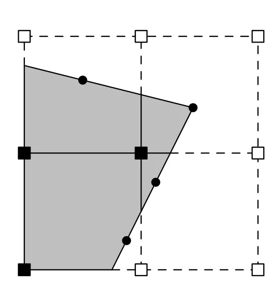
dcnorms.png.1feb72ddfac6a5b2a0863f84d28c1e97.pngdc.png.572cd8b30732a140ad084379680b4078.png
Here's the information we have:
  • We know the exact position of a sign change on one or more edges.
  • We know the normal of the surface at that exact position
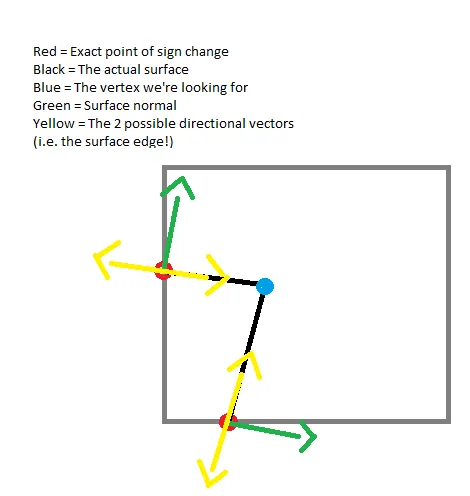
So, how do we find the best vertex for that cell ?
The normal is obviously orthogonal to our surface, so, what does our surface at that point look like ? Of course, it's simply an edge orthogonal to the normal!
That means, there are only 2 possibilities in 2D! (which are essentially kind of the same as they are only the inverse of one another)

newDC.png.5b72dfa878f17e4257d1391f21784165.png
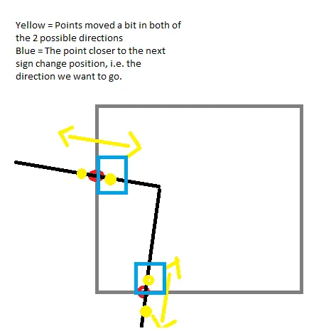
One of the easiest ways to decide which of those 2 directional vectors we need is to simply move our point a bit in each of the directions. The point that's closer to the next sign change is the direction we are looking for.
newDC2.png.d6bb9648e274d68e7c11a15d9f4cde94.png
Now, all we need to do to find the best fitting vertex, is to find the intersection of those 2 directional vectors! (That is, we want to make lines out of those 2 vectors.)
Since we know, that we have 2 or more sign changes in this cell, we know that there is either going to be an intersection of those 2 lines inside of the cell, or none at all.
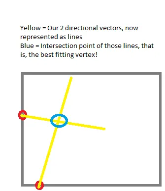
newDC3.png.f819f8e8ae358b022a8c3b22a796b792.png
And that's it! That's what our actual surface looks like.

So, here's all we need to do summarized:
  • For each sign change, calculate the 2 orthogonals to the normal
  • For each other sign change, do the same
  • Look for an intersection between those 2 resulting lines (Essentially, we are looping over all sign changes twice.)

In the end, we simply take the median of all found intersection points (required if there are more then just 2 sign changes)

My approach (3D)

In 3D, there is an infinite amount of orthogonal vectors to our normal, so how do we pick the one representing the edge of our surface ?
In 2D, we can represent the course of a surface in a specific point with the tangent line.
In 3D, the same principal exists. This time, it is a tangent plane.
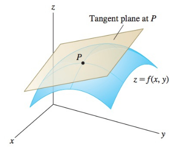
tangent-planes-1.png.8e0414e7d1c2a2ab0c1a7e01a5f5fa41.png
So, instead of 2 vectors as in 2D (the 2 orthogonal vectors to our normal) we have 4 this time. The vector u & v describing the tangent plane, as well as their inverses.
We can apply the same principal as in 2D to find the one vector we are looking for, to represent our surface edge at this point.
Now, all we got to do is to again find the intersection of 2 lines (or more specifically, line segments).

Results in 2D

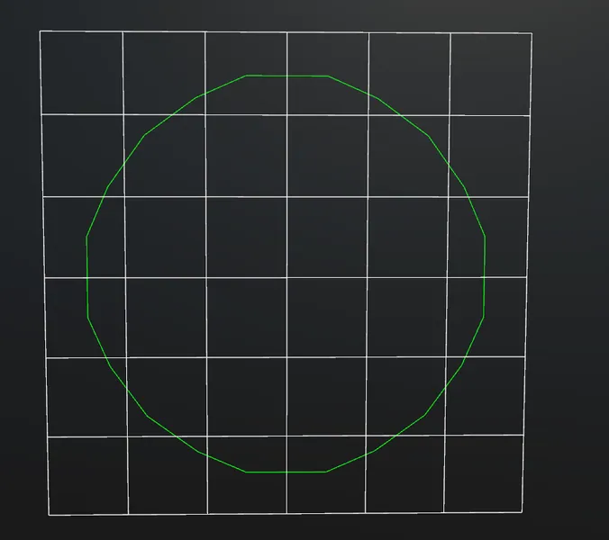
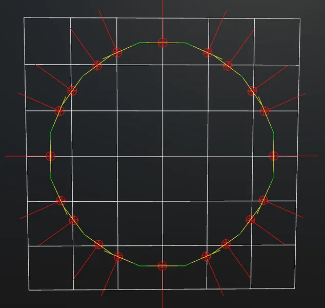
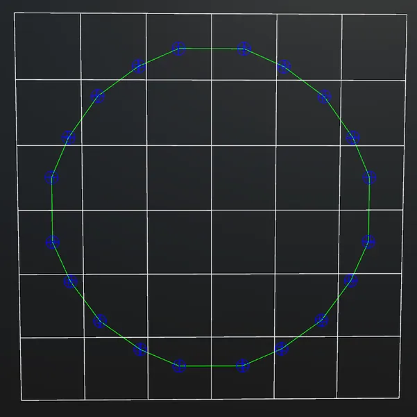
Circle, from left to right: The complete surface, hermite data (sign changes & normals), resulting vertices (points of intersection)
result01.png.56ec771954b0d3d27ee2606a9c885d9f.pngresult01HM.png.65fbeefc347fbd3da50547e7ac6c324a.pngresult01Vertices.png.1e8eace858ec39f0fb3cf6cf80a6db60.png
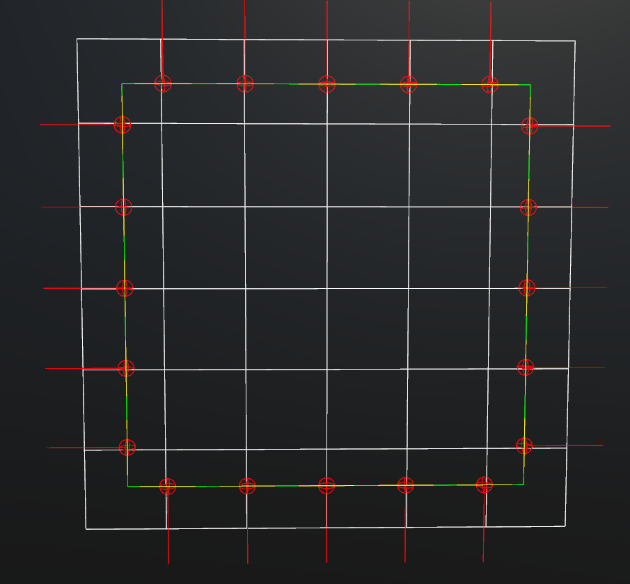
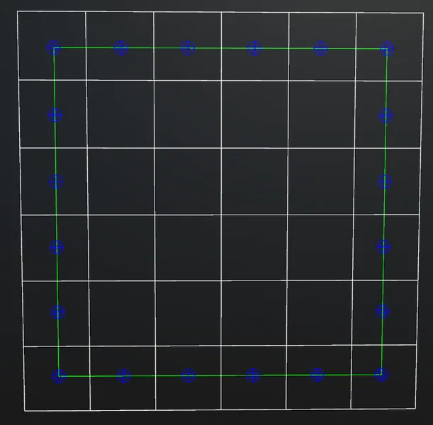
Square, from left to right: The complete surface, hermite data (sign changes & normals), resulting vertices (points of intersection)
result02.png.842a8308e4499138318e7dee357a858c.pngresult02HM.thumb.png.8176e0dc6a7fc282829bec18bec2e4d3.pngresult02Vertices.png.4365a01b0e634c16a8972aae6927d5f3.png

Results in 3D

Left: My approach, right: The result from Boris The Brave's implementation.
https://youtu.be/LtZCa359exU

LifeIsGood
LifeIsGood

I have fixed a few errors in my implementation.
You can see the new results here:


swiftcoder
swiftcoder

Do you have code handy for the 3D case? I'm having trouble visualising what you are doing differently to the original dual contouring implementation.

Tristam MacDonald. Ex-BigTech Software Engineer. Future farmer. [https://trist.am]
LifeIsGood
LifeIsGood

Sure. It's a bit messy right now though. Here's my Solve function (I have not included the intersection function etc. since this is just basic geometry):


    private Vector3 Solve(Vector3[] signChanges, Vector3[] normals)
    {
        var intersections = new List<Vector3>();
        float avrX = 0, avrY = 0, avrZ = 0;

        for (int i = 0; i < normals.Length; i++)
        {
            var n = -normals[i];
            Vector3 u, v;
            GetTangentPlane(n, out u, out v);

            for (int j = 0; j < normals.Length; j++)
            {
                // Do not try to find an intersection point with yourself.
                if (j == i)
                    continue;

                var n2 = -normals[j];

                Vector3 u2, v2;
                GetTangentPlane(n2, out u2, out v2);
              	// When you calculate the tangent plane, you have effectively 4 directional vectors representing your surface
                // (u, v & their inverses)
		// Since we want to "expand" in a specific direction, this method simply figures out which of those 4 vectors to choose.
                var surfDir1 = GetSurfaceDirection(signChanges[i], signChanges[j], u, v);
                var surfDir2 = GetSurfaceDirection(signChanges[j], signChanges[i], u2, v2);

              	// Calculate the intersection point of those 2 line segments 
                // (basically the surface edges from the involved sign changed positions)
                var intersec = GetIntersectionPoint(signChanges[i], surfDir1, signChanges[j], surfDir2);

              	// No intersection.
                if (float.IsNaN(intersec.x) || intersections.Contains(intersec))
                {
                    continue;
                }

                intersections.Add(intersec);
                avrX += intersec.x;
                avrY += intersec.y;
                avrZ += intersec.z;
            }
        }

        if (intersections.Count < 1)
        {
          // This should not happen, since we already know we have at least 2 sign changes here.
	  // So, if we end up in here, something is wrong...
        }
		
      	// Average the position, if there's multiple intersection points.
        // This point now is the vertex we were looking for.
        var vertex = new Vector3(avrX / intersections.Count, avrY / intersections.Count, avrZ / intersections.Count);
        return vertex;
    }

Also, maybe the video I've posted in the comment before helps you to visualize.

Edit:
Idk why I called it solve.... it doesn't solve an equation like the original implementation. Just sticked with it for some reason :D

swiftcoder
swiftcoder

Ok, it looks to me like you are averaging the intersection points of each pair of tangents. Is that correct?

Are the U & V vectors returned by GetTangentPlane() always aligned with the grid in 2 dimensions?

What happens if you run this on a mesh with sharp edges that are not grid-aligned (for example, a cube rotated by 45 degrees)? That's the scenario where dual contouring really shines at producing sharp corners, and I have a feeling that this is going to smooth them out (more along the lines of Surface Nets).

Tristam MacDonald. Ex-BigTech Software Engineer. Future farmer. [https://trist.am]
Gnollrunner
Gnollrunner
4 hours ago, swiftcoder said:

What happens if you run this on a mesh with sharp edges that are not grid-aligned (for example, a cube rotated by 45 degrees)? That's the scenario where dual contouring really shines at producing sharp corners,

Actually this is something I keep wondering about. Every time I look at examples they always show the required point being inside the voxel. However it seems to me that the required point could easily be far outside the voxel which would destroy your sharp corner anyway if you forced it to be inside. I've been shying away from dual contouring for this reason. To me seems like it CAN give you sharp corners but can also easily fail depending on the angle of the corners and the alignment with the grid. Is there something I'm missing here? Perhaps I should take another look at it.

LifeIsGood
LifeIsGood
Quote

Ok, it looks to me like you are averaging the intersection points of each pair of tangents. Is that correct?

Pretty much, yeah. Since we're handling the 3D case there's no tangent, but rather a tangent plane. However, we're only interested in one of the 2 vectors (one of those will resample exactly the surface edge we are interested in), that make up the tangent plane.

Quote

Are the U & V vectors returned by GetTangentPlane() always aligned with the grid in 2 dimensions?

No. The tangent plane can have any orientation, as you can see here:
https://www.khanacademy.org/math/multivariable-calculus/applications-of-multivariable-derivatives/tangent-planes-and-local-linearization/a/tangent-planes

Quote

What happens if you run this on a mesh with sharp edges that are not grid-aligned (for example, a cube rotated by 45 degrees)? That's the scenario where dual contouring really shines at producing sharp corners, and I have a feeling that this is going to smooth them out (more along the lines of Surface Nets).

I think it should work. I'll reply back with some results once I've tested that.

LifeIsGood
LifeIsGood

There is indeed a problem with sharp features when averaging the intersection points, as you can see in this video.
However, it is not as prevalent as it is with Marching Cubes.

Notice the intersection points (in light blue / cyan) and the generated vertex (in dark blue)
The averaging smoothes out the corners. I'm currently looking for a better solution then simply averaging the intersection points.
Ideally, the generated vertex would lie right above the lower intersection point, creating a normal corner.

https://youtu.be/PXKI1PWlmt0


Quote

However it seems to me that the required point could easily be far outside the voxel which would destroy your sharp corner anyway if you forced it to be inside

This is a misconception about how the algorithm actually works.
2 or more sign changes per grid cell mean, the function changes here from non solid to solid (or vice versa), so no matter what kind of surface we have in this space, the vertex we're looking for is guaranteed to lie inside this cell.

So, when the QEF returns a point outside the cell, it's actually just an "error" of the applied solution.

Gnollrunner
Gnollrunner
45 minutes ago, LifeIsGood said:

This is a misconception about how the algorithm actually works.
2 or more sign changes per grid cell mean, the function changes here from non solid to solid (or vice versa), so no matter what kind of surface we have in this space, the vertex we're looking for is guaranteed to lie inside this cell.

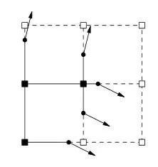
OK here's an example. We have a couple edges coming into a voxel (two sign changes). The arrows are the normals from the Hermite data. Where would we put the intersection to retain a sharp corner? I don't see how it's possible but perhaps I'm missing something.

Dual.jpg

LifeIsGood
LifeIsGood

Ah, I see what you mean. There's no need to create a vertex here, since there's going to be no intersection inside of this cell (keep in mind that we are working with line segments) the vertex will be generated in the cell above this one.

If the corner is outside of the grid's bounds, well, then you simply don't have enough space to generate the whole mesh.

I am not too sure how standard DC would handle this, but here's my guess:
- You would simply snap the vertex into the cells bounds and you would still get a sharp feature, since we're going to create another vertex in the cell above.

swiftcoder
swiftcoder
39 minutes ago, LifeIsGood said:

I am not too sure how standard DC would handle this

Many dual contouring implementations don't clamp in this sort of case. Those that do mostly just fall back to the mass point (i.e. average of intersections). Very few implementations actually handle this case gracefully :)

Tristam MacDonald. Ex-BigTech Software Engineer. Future farmer. [https://trist.am]
Gnollrunner
Gnollrunner
7 hours ago, LifeIsGood said:

- You would simply snap the vertex into the cells bounds and you would still get a sharp feature, since we're going to create another vertex in the cell above.

The only thing is there is no sign change in the cell above, so as far as the algorithm goes the vertex would have to be associated with this voxel. However I guess that could still work, although allowing the vertex to fall outside to voxel means you can no longer use the grid to help with collision. It's possible the vertex could even be several voxels away for very sharp angles.

LifeIsGood
LifeIsGood

There are definitely 2 sign changes in the cell above in the sample drawing you habe provided.

The only time where that would not be the case, is if the corner would lie directly on the edge of a cell.

Gnollrunner
Gnollrunner
35 minutes ago, LifeIsGood said:

There are definitely 2 sign changes in the cell above in the sample drawing you habe provided.

The only time where that would not be the case, is if the corner would lie directly on the edge of a cell.

There are two sign changes but only as far as the function/data goes. The problem is both sign changes occur on the same edge, so if you look at just the corners of the box above this one you won't see any sign changes. The corners will all be either plus or minus.

Dual2.jpg

Gnollrunner
Gnollrunner

I just realized there might be one more problem with letting the point fall outside the box. If you are tying for destructible geometry, clearing out a voxel that a neighboring voxel has projected a point into will do nothing.

LifeIsGood
LifeIsGood

You don't have to compare the corners, you can compare any values lying on the edge. It's just the most compelling way to choose the corners.

However, if that's what you worry about, then you likely are simply using a grid resolution inappropriate for your SDF.

Quote

I just realized there might be one more problem with letting the point fall outside the box. If you are tying for destructible geometry, clearing out a voxel that a neighboring voxel has projected a point into will do nothing.

See swiftcoder & my posts. If you are not handling this case, well, then you are simply accepting the fact, that the generated mesh is going to be a bit more imprecise.

Gnollrunner
Gnollrunner
1 minute ago, LifeIsGood said:

You don't have to compare the corners, you can compare any values lying on the edge. It's just the most compelling way to choose the corners.

However, if that's what you worry about, then you likely are simply using a grid resolution inappropriate for your SDF.

I still see a few problems. No matter what grid resolution you pick, I can still create cases for which it will fail. You will of course generate a better corner as you go down to a smaller grid, but the algorithm can never guarantee a perfect corner, unless you have some way of subdividing unevenly which creates a another whole complexity.

Also it seems to me that checking many places along along the edge can be rather costly depending upon your function/data, and additionally if you find sign changes you will still have to subdivide the voxel if you want to use the same algorithm. Depending on where the sign change is, you may have to subdivide the voxel several times if you are subdividing it evenly.

Finally the sign changes may not even be on an edge. You can imagine a case where a spike pokes through a face and you don't get any sign changes at all on an edge, only somewhere on a face.

I think perhaps allowing a vertex to fall outside it's voxel solves some of these things but then you have other issues to deal with.

LifeIsGood
LifeIsGood
Quote

I still see a few problems. No matter what grid resolution you pick, I can still create cases for which it will fail.

Of course you can, you are using a grid. You will always be bound to it's resolution. As you will always have some sort of aliasing with a pixel display. That's just the way it is.

However, reality shows us, that the results are good enough in most use cases. How likely is the case on your first drawing ? If you generate so many small polygons, you'll have to deal with other problems anyways.

Quote

Finally the sign changes may not even be on an edge. You can imagine a case where a spike pokes through a face and you don't get any sign changes at all on an edge, only somewhere on a face

How likely is this case ? What kind of surface do we have that we could ever experience this kind of problem ?
Practice shows us, that none of this is really likely to happen.

If it does in your case, find a way to fix your problem!

Gnollrunner
Gnollrunner
9 minutes ago, LifeIsGood said:

How likely is the case on your first drawing ?

How likely? I think it's very likely, close to 100% unless you are specifically aligning your data with your grid and using corners which aren't too sharp. This is typically the use case I see in examples. I was hoping there was some more general solution which is why I'm discussing this. I'll admit that with terrain, it's not such a big deal since you don't really need exact corners in most cases. Sharp corners are mostly needed for man made stuff such as houses and so forth.

Quote

If it does in your case, find a way to fix your problem!

Well currently it's not my problem since I'm not using dual contouring at this point. I'm using a primal (marching) algorithm since I'm dealing with terrain and I'm trying to avoid non-manifold geometry . That may change if I find some better solution.

BTW I'm not coming down on your work in any way. I hope you didn't take my comments this way. I think the basic dual contouring algorithm has these issues. Marching algorithms have other issues. I'm just trying to hash out any problems and find possible solutions. In fact I did learn something. I hadn't really considered simply letting the point fall outside the voxel. In my case since I'm not targeting destruction of buildings and such, that might be an option I want to try later when I get to that point.

LifeIsGood
LifeIsGood
Quote

How likely? I think it's very likely, close to 100% unless you are specifically aligning your data with your grid and using corners which aren't too sharp

I don't think that's accurate, if you are using a grid with a proper size related to your SDF.
If you have a cube the size of 1 single of your grid cells, then it's pretty likely to run into those problems. But it's also really likely to run into different problems such as finding sign changes at all with this kind of size.
Generally, your grid should have a lower resolution then your surface, otherwise you are also likely to run into problems with multiple surfaces in one single cell (aka manifold surfaces)

Quote

Well currently it's not my problem since I'm not using dual contouring at this point.

I think that's your problem. It's really hard to think about this kind of problem. Once you have a bunch of results & debug information, it's a lot easier to think about it. (That's why I'm showing all this debug information in different colors, like sign changes, normals, surface edges, intersection points, etc.)

Quote

BTW I'm not coming down on your work in any way. I hope you didn't take my comments this way.

Absolutely not. I just think you are overthinking your situation. That's what I mean when I say "find a way to fix your problem". Get some results. Once you have those, identify your problems. Then, fix those problems.


Edit:

Quote

just realized there might be one more problem with letting the point fall outside the box. If you are tying for destructible geometry, clearing out a voxel that a neighboring voxel has projected a point into will do nothing.

Actually, if you let your vertex fall outside of the cell there would be no problem with clearing the adjacent cell.
Because if you do, you will have to adjust the SDF of your surface, meaning there will be no more surface in this cell.

Edit 2:

It might be even better to simply let the vertex fall outside. You would just have to deal with multiple same vertices perhabs. I don't know without testing.

Topic Locked

This topic has been locked by a moderator. New replies are not allowed.

Sign in to reply to this topic.