Advertisement

Mesh LOD selection

Started by October 01, 2024 11:49 PM
9 comments, last by frob 2 months, 1 week ago

Hi!
Here a mesh LOD selection code:

size_t ComputeMeshLODIndex(const Vector3& cameraPosition, const float cameraFOV, const uint32_t viewportHeight, const AxisAlignedBoundingBox& aabb, const size_t lodCount)
{
    if (lodCount < 2)
    {
        return 0;
    }

    const float cameraToAABBLength = (aabb.ComputeCenter() - cameraPosition).Length();
    if (cameraToAABBLength < Math::epsilon)
    {
        return 0;
    }

    const size_t lastLODIndex = lodCount - 1;
    const float aabbProjectedRadius = (aabb.ComputeRadius() * viewportHeight) / (2.0f * cameraToAABBLength * Math::Tan(0.5f * cameraFOV));
    const float screenHeightCoverage = aabbProjectedRadius / viewportHeight;
    const float lodIndex = (1.0f - screenHeightCoverage) * lastLODIndex;
    return Math::Min(static_cast<size_t>(lodIndex), lastLODIndex);
}

Is there a better recommended way for LOD selection?
Thanks!

EDIT: I just found this link:
https://iquilezles.org/articles/sphereproj/
Can be part of the discussion.

Eventually i miss the log2 in your code.

Fro example:

float lodF = max(0.f, log2(distance * modelDetail));
int lodI = int(floor(lodF));
lodF = min(lodF - float(lodI), 1.f);

If we were using mipmaps, lodI would give us the level, and lodF would give the fraction to blend with the next. (Ofc. for meshes we can't do such blending.)

modelDetail could be calculated from the average edge length of the model times user detail setting, but not from the total size of a bounding box.

There should be a way to explain this better, but i think it leads to what you want.

Alundra said:
EDIT: I just found this link: https://iquilezles.org/articles/sphereproj/ Can be part of the discussion.

There is a problem with using pixel coverage: If you rotate the camera with some higher fov setting, the model becomes twice as large on the edges of the screen than at it's center. (That's the error of planar perspective projection, which can be avoided only with ‘spherical/fisheye/bodycam’ projection, but that's incompatible with standard rasterization.)
So you would switch lods already on camera rotation, which probably isn't good.
A metric only based on distance avoids this.
The log2 in the function makes sure that each lower lod is visible for a range of twice the distance than the former higher lod.

Edit: Being uncertain i've tried this example, but it works as intended:

static float modelDetail = 0.3f; ImGui::DragFloat("modelDetail", &modelDetail, 0.01f);
			for (int i=0; i<1000; i++)
			{
				float distance = float(i) * modelDetail;
				float lodF = std::max(0.f, log2(distance * modelDetail));
				int lodI = int(floor(lodF));
				lodF = std::min(lodF - float(lodI), 1.f);
				if (i%10 == 0) Vis::RenderLabel(sVec3(distance,lodF*10,0), Vis::RainbowR(lodI*0.2f),Vis::RainbowG(lodI*0.2f),Vis::RainbowB(lodI*0.2f), "%i", lodI);
			}
Advertisement

So, your opinion about this if I understand well is to not use any screen coverage metric but only the distance of camera to entity.

Alundra said:
So, your opinion about this if I understand well is to not use any screen coverage metric but only the distance of camera to entity.

There are technical arguments to it, e.g. if switching LOD generates costs like streaming from disk or rebuilding RT BVH. Usually we want to minimize switching.
Or we could say that minimizing lod switches also reduces popping for a better player experience.
These arguments depend on practical cases and personal opinion.

But in general, opinions aside, i still think this log2 equation is the default, or reference.
This is because it is used for mip mapping to select the two texture levels (and their blending weights), so we use the texture resolution matching our display resultion as well as possible.

Now you may feel like selecting lods of geometry is an entirely different problem, but ideally it's not. Ideally we have levels of detail where each one is of about half resoltion of the former, and so the math and problem is the exact same. Mip mapping is the reference example for a perfect LOD solution.
But there are some more details to it, e.g. the problem of how player FOV settings should affect our LOD selection. I guess we can calculate a constant scaling factor (affecting ‘modelDetail’ of my code) from the fov angle with some simple trigonometry, but not sure. (I see that tan in your code now : )

Looking at your code closely i assume it works to select from the first two levels. But then it would switch too quickly to the higher levels. Adding the log2 would fix this. Pretty sure about that.

Probalbly mixing adding the log2 in my previous code would improve the switch. Sounds good mix.

My code simply project the AABB radius (making the AABB a bounding sphere) on screen, then you have the coverage dividing with the screen height giving a float ratio.

This float ratio is then used as LERP (but snapping by floor) for the LOD, but yes you right for mipmap log2 is prefered, like for IBL.

size_t ComputeMeshLODIndex(const Vector3& cameraPosition, const float cameraFOV, const uint32_t viewportHeight, const AxisAlignedBoundingBox& aabb, const size_t lodCount)
{
    if (lodCount < 2)
    {
        return 0;
    }

    const float cameraToAABBLength = (aabb.ComputeCenter() - cameraPosition).Length();
    if (cameraToAABBLength < Math::epsilon)
    {
        return 0;
    }

    const size_t lastLODIndex = lodCount - 1;
    const float aabbProjectedRadius = (aabb.ComputeRadius() * viewportHeight) / (2.0f * cameraToAABBLength * Math::Tan(0.5f * cameraFOV));
    const float screenHeightCoverage = aabbProjectedRadius / viewportHeight;
    const float screenHeightCoverageLog2 = Math::Log2(1.0f + screenHeightCoverage);
    return static_cast<size_t>((1.0f - Math::Min(screenHeightCoverageLog2, 1.0f)) * lastLODIndex);
}

What about this version using projection matrix?

size_t ComputeMeshLODIndex(const Vector3& cameraPosition, const Matrix4& projectionMatrix, const AxisAlignedBoundingBox& aabb, const size_t lodCount)
{
    if (lodCount < 2)
    {
        return 0;
    }

    const Vector3 aabbCenter = aabb.ComputeCenter();
    const Vector3 cameraToAABB = aabbCenter - cameraPosition;
    const Vector4 projectedCenter = projectionMatrix.Transform(Vector4(cameraToAABB.m_x, cameraToAABB.m_y, cameraToAABB.m_z, 1.0f));

    const float aabbRadius = aabb.ComputeRadius();
    const Vector3 cameraToAABBRadius = Vector3(aabbCenter.m_x, aabbCenter.m_y + aabbRadius, aabbCenter.m_z) - cameraPosition;
    const Vector4 projectedCenterWithRadius = projectionMatrix.Transform(Vector4(cameraToAABBRadius.m_x, cameraToAABBRadius.m_y, cameraToAABBRadius.m_z, 1.0f));

    const float projectedRadius = Math::Abs((projectedCenterWithRadius.m_y / projectedCenterWithRadius.m_w) - (projectedCenter.m_y / projectedCenter.m_w));
    const float screenCoverage = Math::Min(projectedRadius, 1.0f);

    const size_t lastLODIndex = lodCount - 1;
    return static_cast<size_t>((1.0f - screenCoverage) * lastLODIndex);
}
Advertisement

Involving the projection makes sense, since it affects how much smaller things appear on screen with increasing distance.
But notice it is actually only the fov angle (actuially its sine) which matters, so you could optimize. A matrix multiply isn't needed.

If you do the complete projection, i'm afraid the problem of lod depending on camera angle comes back.
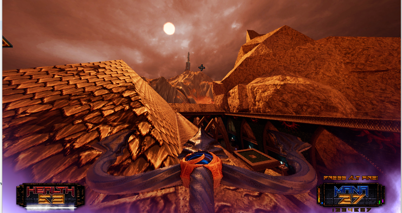
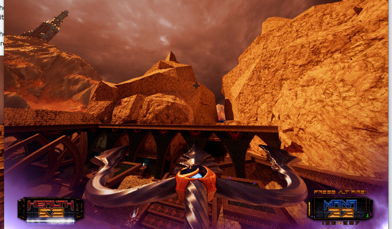
Don't underestimate this. Here's a screenshot:

Not moving, just rotating my view:

Look how much bigger the distant tower becomes. It's twice as large on screen, just becasue it's on the edge now.

You don't want lod popping just becasue players rotate their view.

Nitpicking about variable names, you map ‘coverage’ to ‘size’ (radius). This is actually wrong, since coverage is a metric of 2D area, not 1D size. Coverage = radius * radius would make more sense. ; )

Good point about the naming, it's good you mentionned it, “projectedRadiusClamped” is probably more correct.
Or simply add the min part of the calculation:

const float projectedRadius = Math:Min(Math::Abs((projectedCenterWithRadius.m_y / projectedCenterWithRadius.m_w) - (projectedCenter.m_y / projectedCenter.m_w)), 1.0f);

Actually the previous code can be changed like that:

size_t ComputeMeshLODIndex(const Vector3& cameraPosition, const Matrix4& projectionMatrix, const AxisAlignedBoundingBox& aabb, const size_t lodCount)
{
    if (lodCount < 2)
    {
        return 0;
    }

    const float cameraToAABBLength = (aabb.ComputeCenter() - cameraPosition).Length();
    if (cameraToAABBLength < Math::g_epsilon)
    {
        return 0;
    }

    const float aabbRadius = aabb.ComputeRadius();
    const Vector3 cameraToAABBRadius = Vector3(0.0f, aabbRadius, cameraToAABBLength);
    const Vector4 projectedCameraToAABBRadius = projectionMatrix.Transform(Vector4(cameraToAABBRadius.m_x, cameraToAABBRadius.m_y, cameraToAABBRadius.m_z, 1.0f));

    const size_t lastLODIndex = lodCount - 1;
    const float projectedRadius = Math::Min(projectedCameraToAABBRadius.m_y / projectedCameraToAABBRadius.m_w, 1.0f);
    return static_cast<size_t>((1.0f - projectedRadius) * lastLODIndex);
}

Which is also what Quake3 was doing, put the AABB like front of the camera and project the radius on Y-axis:
https://github.com/id-Software/Quake-III-Arena/blob/dbe4ddb10315479fc00086f08e25d968b4b43c49/code/renderer/tr_mesh.c#L26

You might also consider view-dependent continuous level of detail (CLOD) systems and the over 30 years of research into them, particularly in regards to terrain where a lot of the research originated.

The number of pixels affected is one of several measures. For meshes the visual error on the silhouette or material edges is a very important one for humans, more important than internal visual error. It's more visually important to see the tiny jagged edges on the transition zone than to see the jagged mesh pieces in the central core. For textures it is often the opposite, texture details on curved edges near boundaries is often less important than detail in the flat areas facing us.

These importance values of the view-dependent details can be exaggerated in certain rendering techniques, particularly cel-shaded and painterly art styles. Increasing the mesh complexity inside a cel-shaded object won't result in any visual difference; even though the model has more complex information it results in the same 2-tone or 3-tone rendered image. But increasing the complexity on the internal and external silhouette lines can dramatically alter the rendered image, even though it is 2-tone or 3-tone there will be more variation and details shown to the viewer.

This topic is closed to new replies.

Advertisement