GameDev.net gamedev.net
🔒 Locked

Shader interp problem

Started by happygl Feb 21 at 5:08 PM 51 replies 3.2k views
Original Post
happygl
happygl

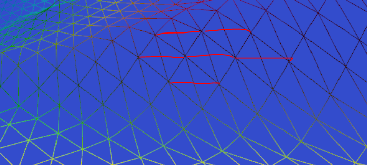
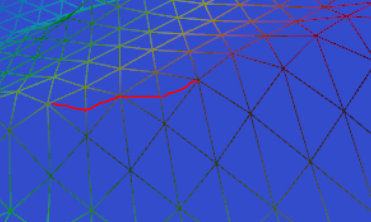
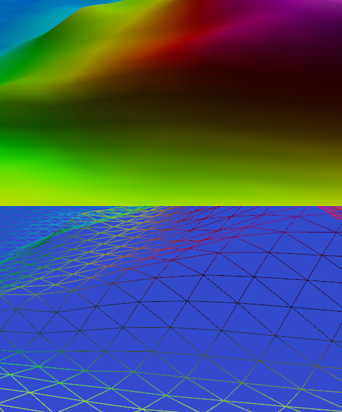
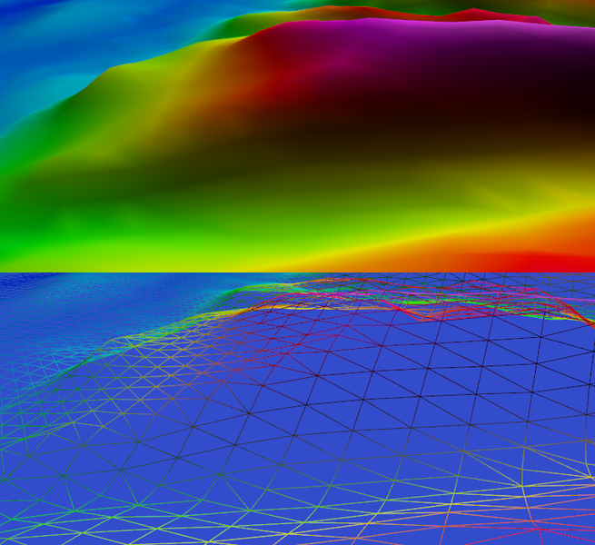
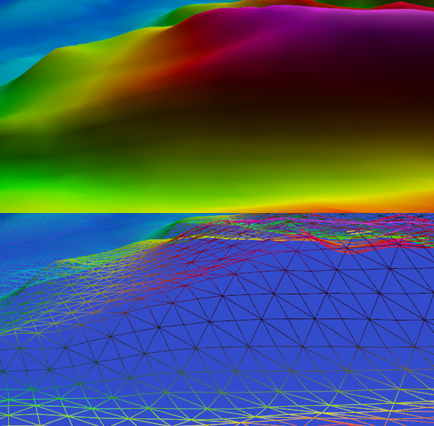
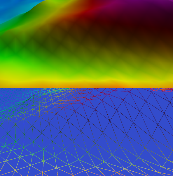
Hello, been doing OpenGL for 20 years now, but never done lighting with glsl. Trying to get it to work but I've got this weird grid effect. I've shown here the shaded mesh and the wireframe. The edges of the triangles are darker except for the long side which is lighter. Anyone got any idea how this is happening? Normals are normalized everywhere (code, vertex, fragment). This seem to occur on the ‘dark side’ of the hills, though the lighting vector is steep enough to illuminate them with its diffuse only (which is the only lighting component).
JoeJ
JoeJ

It's maybe not a bug but just the usual and expected artifacts from vertex lighting, but hard to say.

To figure out it would be good if you could quickly alternate the diagonal edge splitting a quad into 2 triangles like so:

For this part of the scene it should fix it, and if it does, we know that's the problem.

I am not sure if switching to per pixel lighting would help as well. Because it works on top of interpolated vertex normals i guess it does not.

So the only way to fix it properly would be to align the splitting edge to each quad individually (which also gives better physics regarding collisions).
The goal is to find the direction of primary curvature and pick the closest edge to that. Neither picking the shorter edge, nor using Delaunay triangulation rules helps here.
I have worked on this before and should be able to help if you want to do this. But my current solution is overcomplicated and i'd need to simplify.

RmbRT
RmbRT

Do adjacent triangles share the same vertex? It could be helpful to only render the vertex normals, not the lighting. My bet is there is either something wrong with the normals, or with the lighting formula. I used the same approach you're trying to use and never had problems.

Walk with God.
JoeJ
JoeJ

RmbRT wrote:

My bet is there is either something wrong with the normals, or with the lighting formula.

I don't think so. Another drawing to show what happens:

I tried to divide the diagonals at their center, drawing straight lines to vertices, showing the typical zig zag bumps which happen from edge flow with bad curvature alignment. The lighting is correct, but the geometry is bad. You see the zig zag if you rotate the camera accordingly, and it can get very bad.

I was annoyed from this issue even with professional modeling tools. No tool i ever used was able to pick the proper diagonal to fix this. I wonder why it's so rarely discussed and seemingly just accepted by everybody.

A solution is possible, but at the cost of unique diagonal per quad, breaking the regular mesh structure (variable number of edges per vertex, eventually more memory).

happygl
happygl

JoeJ, thank you for you input. I have rotated the triangles around, and it certainly looks different now. Could not get the exact view as before, but the orientation is clearly making a big difference. Of course, I cannot determine which way round the triangles should go - a difficult problem which is probably why you have not seen tools that fix this - it might also depend on the lighting direction.

What you seem to be saying is that dividing the quad into four triangles via an additional centre vertex will fix this issue? I think this removes the directionality from the triangle mesh, which is presumably what's causing this strange gridding issue.

This is an option I could consider as my performance budget has capacity.

happygl
happygl

Not sure where the image went.

JoeJ
JoeJ

happygl wrote:

it might also depend on the lighting direction.

No, luckily it only depends on the curvature of the geometry.

happygl wrote:

What you seem to be saying is that dividing the quad into four triangles via an additional centre vertex will fix this issue?

No, i would only 'rotate' the diagonal edge slicing each quad into two triangles.
(Although for for my visualizations i do often use an additional center vertex with 4 new diagonal edges as well, because it's trivial and helps. But ofc. that's very inefficient.)

Not sure where the image went.

Maybe it took some time to appear after the upload, but i can see it.
It's mostly better for this area, as expected.

So i'll work an a simple method to find the ideal splitting edge per quad.
But that's some work to setup a test case, so might take some days til i get at it.

My idea is to calculate vertex normals from the quad mesh, then accumulate dot products for both potential diagonal edges, and comparing sums to decide for the better split.
But i need to try. In cases where curvature is zero (or low) we can't decide based an curvature, and i used a fallback to Delaunay for those cases. So i needed to calculate both curvature direction and Delaunay per quad, which is pretty complex.
It feels like simple problem and there should be a trivial solution. I'll report what i find...


RmbRT
RmbRT

It doesn't matter what the topology is, what matters is whether topology affects the normals. If you first choose a topology and then choose the normals based on the resulting triangles, you will invariably get bad artifacts. If you choose the normals of each vertex based on the heightmap, not on its triangularisation, then only with grossly insufficient triangle resolution will you get any visible artifacts at all.

I have repeatedly done vertex lighting on randomly generated heightmap meshes and never had any of the issues shown here. And I had used the same simple topology for triangles, simple heightmap squares divided into two triangles.

Walk with God.
JoeJ
JoeJ

RmbRT wrote:

If you choose the normals of each vertex based on the heightmap, not on its triangularisation, then only with grossly insufficient triangle resolution will you get any visible artifacts at all.

Show more

'Based on heightmap' is equivalent to 'calculating vertex normals from the initial quads', and it can help, but badly chosen diagonals always cause issues where curvature is high enough.

Imagine a steep canyon going along the diagonal of the map, causing a sharp angle like 30 degrees at the bottom.
If you pick the wrong diagonal to split the quads, the zig zag will be harsh, causing bumps with 30 degrees too. And it does not get better with increasing resolution. Tessellation always matters.

(I don't say uniform diagonals should never be used. Most heightmaps in games just accept the issue, since they already need to avoid sharp angles due to vertical texture stretching. But i'm sure the improvement would be worth it in most cases.)

Regarding your bad normals obtained from triangles, this sounds like your method of normal calculations is the cause. Averaging adjacent triangle normals as common is low quality. Area weighted normals isn't good either in my experience. I found angle weighted normals by far the best, also solving the problem you see.

But using the heightmap values may be still superior, i can't tell.
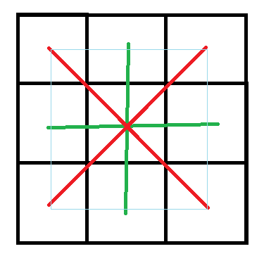
However, there are quality options with this too. Using just the 4 horizontal and vertical neighbours is low quality. Adding the diagonals as well with half the weight is much better:


The high quality normal should be: normalize(red cross normal * 2 + green cross normal), resembling a properly area weighted box filter. (ignoring details such as redundant normalization optimizations and area from height differences)

Makes a big difference for erosion simulation for example, and i guess it helps with gfx too.
But choice of triangulation edge still matters. Just the potential error becomes smaller due to a wider blur.

RmbRT wrote:

never had any of the issues shown here.

You did not look close enough.
I can even see such artifacts on character faces of AAA games, even if artists spend the time to flip bad edges manually.
It's hard to unsee once you are aware.


EDIT: I realize my heightmap example depicts hq cell (or face) normals, but not vertex normals as discussed here. For vertex normals just move the black grid by half a cell, leaving us with a 3x3 region of relevant vertices. Method remains the same otherwise.

happygl
happygl

I have tried several approaches to solve the problem.

The first, I found the centre point, and compared the height difference to the underlying heightfield to the centre point along the diagonal line. The triangle orientation that gave minimal error was selected. This looked awful.

The second approach was just to look at the two sets of triangles and choose the one with the minimum difference between the normals. This looked even worse.

On a hunch I tried the maximum difference between the normals. This actually looked reasonably good, don't know why.

For the third approach tried adding a point in the centre of the quad, the “4-triangle quad”. This has no orientation.

This looks better but still has artefacts. It looking better could of course just be the result of a larger number of triangles, but I could reduce the sampling to compensate.

To answer RmbRT's question - it's a clean mesh with shared vertices, the normals are calculated from the triangles and the shader is just FragColor=dot(normal,light)*tex_sample with everything normalized everywhere.

RmbRT
RmbRT

Yeah, calculating normals from the triangles is bound to get you into trouble, because the triangularisation already produces artifacts that do not exist on the “ideal” thing the mesh represents. I created my terrain models from the heightmap grid, with no subdivision, if I remember correctly, just two triangles per grid tile. Or actually, I think I may have used 4 triangles per square because otherwise the center point of a square only knows of 3 surface normals instead of 4. It's been 10 years or so, I can't quite remember.

But even if you only have 2 triangles per quad, while it would only interpolate between 3 normals instead of 4, it should still not generate the artifacts you showed initially, where somehow the center of each tile is brighter than all its borders and than all corner points.

Another thing that could cause it is if your texture is not loaded as sRGB, but just RGB. You either have to tag your texture as sRGB when uploading the texture data, or you have to manually transform the texture values into linear light before applying light calculations to it. And then transform it back into sRGB. Which you also need to do manually or via glEnable(GL_FRAMEBUFFER_SRGB). In general, you can't just do linear light calculations and write them to the framebuffer. That always results in artifacts with wrong brightness.

Walk with God.
happygl
happygl

To make a normal, you need the cross product. That needs exactly two vectors, which is basically a triangle. So however you want to make normals you need triangles (not quads). So however you're making normals you are basically triangulating. But you are saying you use a different triangle set than the drawn mesh - I don't see how this would fix anything. Sure, it might work, as in look ok, and I've actually done this myself in the past when I had to, but here I have different tiles sampling an underlying height field at different sampling distances for LoDs; I cannot use normals generated from a higher triangulation level in a lower resolution level - I have done this before and it looks awful.

I have been able to confirm that I get the same artefacts with the OpenGL fixed pipeline - glEnable(GL_LIGHT) etc, so my title of ‘Shader interp problem’ is not accurate.

The ‘extra point in a quad’ method has other artefacts elsewhere on the grid, like ridges that now become spiky. So I think I'll just leave my fixed ‘SW to NE’ triangle split. Running the engine at the triangle size/count I intend to (about two quad divisions down in the images) makes the problem go away anyway - presumably this is what everyone does.

RmbRT
RmbRT

I calculated the normals of the corner points of the height map grid. I think I may simply have used the 4 lines connecting it to its 4 neighbours, and calculated an average normal from that. But I no longer have that 10 years old code around, so I don't know what exactly the method was.

Walk with God.
JoeJ
JoeJ

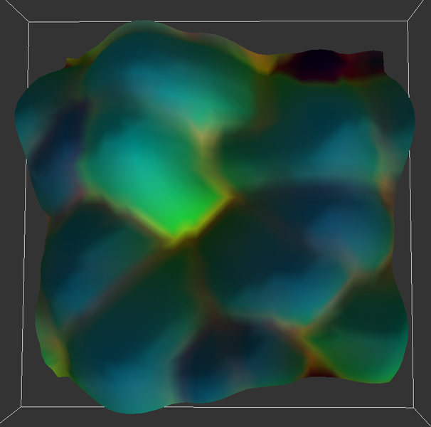
I have tried the method i've had in mind, and it works pretty well:

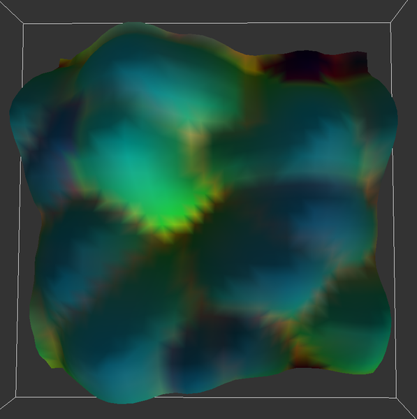
For comparison, flipping the result to show the worst case:

I have not compared against my complex reference method, but on the heightmap it definitively works, and it's super simple. : )

Here is the code, see the second loop. Just summing up vertex normals - split edge dot products and compare.

(can't paste code due to new forum, trying a new post...)

JoeJ
JoeJ
if (1) // test curvature aligned triangualtion
		{
			struct Vertex
			{
				vec pos;
				vec norm;
				vec col;
			};

			std::vector<Vertex> vertices (res * res);
			for(int iV = 0; iV < res; iV++) 
			for(int iU = 0; iU < res; iU++)
			{
				int i = iV * res + iU;
				int a0 = iV * res + ((iU+1)&mask);
				int a1 = iV * res + ((iU-1)&mask);
				int a2 = ((iV+1)&mask) * res + iU;
				int a3 = ((iV-1)&mask) * res + iU;

				float h = texture[i][3];
				float h0 = texture[a0][3];
				float h1 = texture[a1][3];
				float h2 = texture[a2][3];
				float h3 = texture[a3][3];

				vec x0 ( (float(iU+1)+.5f) / float(res), (float(iV)+.5f) / float(res), h0 * visSclA);
				vec x1 ( (float(iU-1)+.5f) / float(res), (float(iV)+.5f) / float(res), h1 * visSclA);
				vec x2 ( (float(iU)+.5f) / float(res), (float(iV+1)+.5f) / float(res), h2 * visSclA);
				vec x3 ( (float(iU)+.5f) / float(res), (float(iV-1)+.5f) / float(res), h3 * visSclA);
				vec n = vec(x0-x1).Cross(x2-x3).Unit();

				float l = 1.f;
				if (lightContrib != 0)
					l = (1.f-lightContrib) + Light(n) * lightContrib;

				float r = visSclR * l * mR.AddValue(texture[i][0]);
				float g = visSclG * l * mG.AddValue(texture[i][1]);
				float b = visSclB * l * mB.AddValue(texture[i][2]);

				vec x ( (float(iU)+.5f) / float(res), (float(iV)+.5f) / float(res), h * visSclA);

				//RenderLine(x,(x0+x)*.5f, 1,0,0);
				//RenderLine(x,(x1+x)*.5f, 0,1,0);
				//RenderLine(x,(x2+x)*.5f, 0,0,1);
				//RenderLine(x,(x3+x)*.5f, 1,1,0);
				//RenderPoint(x, r,g,b);

				Vertex vertex;
				vertex.pos = x + origin;
				vertex.norm = n;
				vertex.col = vec(r,g,b);
				vertices[i] = vertex;
			}

			for(int iV = 0; iV < res-1; iV++) 
			for(int iU = 0; iU < res-1; iU++)
			{
				Vertex v0 = vertices[iV*res+iU];
				Vertex v1 = vertices[iV*res+iU+1];
				Vertex v2 = vertices[(iV+1)*res+iU];
				Vertex v3 = vertices[(iV+1)*res+iU+1];

				vec diag0 = v3.pos - v0.pos;
				vec diag1 = v2.pos - v1.pos;
				//diag0.Normalize(); // no!
				//diag1.Normalize(); 

				float dot0 =	fabs(diag0.Dot(v0.norm)) + 
								fabs(diag0.Dot(v1.norm)) + 
								fabs(diag0.Dot(v2.norm)) + 
								fabs(diag0.Dot(v3.norm));
				
				float dot1 =	fabs(diag1.Dot(v0.norm)) + 
								fabs(diag1.Dot(v1.norm)) + 
								fabs(diag1.Dot(v2.norm)) + 
								fabs(diag1.Dot(v3.norm));
				
				if (dot0 > dot1)
				{
					//RenderLine (v1.pos, v2.pos, 1,1,1);
					simpleVis.RenderTriangle (	
						(float*)&v2.pos, (float*)&v2.col,
						(float*)&v1.pos, (float*)&v1.col,
						(float*)&v3.pos, (float*)&v3.col );
					simpleVis.RenderTriangle (	
						(float*)&v1.pos, (float*)&v1.col,
						(float*)&v2.pos, (float*)&v2.col,
						(float*)&v0.pos, (float*)&v0.col );
				}
				else
				{
					//RenderLine (v0.pos, v3.pos, 1,1,1);
					simpleVis.RenderTriangle (	
						(float*)&v2.pos, (float*)&v2.col,
						(float*)&v0.pos, (float*)&v0.col,
						(float*)&v3.pos, (float*)&v3.col );
					simpleVis.RenderTriangle (	
						(float*)&v0.pos, (float*)&v0.col,
						(float*)&v1.pos, (float*)&v1.col,
						(float*)&v3.pos, (float*)&v3.col );
				}
			}			
		}
JoeJ
JoeJ

I've added the higher quality normals as mentioned above, considering the diagonal neighbors as well.
Switching on and off the improvement is noticeable.


JoeJ
JoeJ
std::vector<Vertex> vertices (res * res);
			for(int iV = 0; iV < res; iV++) 
			for(int iU = 0; iU < res; iU++)
			{
				int i = iV * res + iU;
				int a0 = iV * res + ((iU+1)&mask);
				int a1 = iV * res + ((iU-1)&mask);
				int a2 = ((iV+1)&mask) * res + iU;
				int a3 = ((iV-1)&mask) * res + iU;

				float h = texture[i][3];
				float h0 = texture[a0][3];
				float h1 = texture[a1][3];
				float h2 = texture[a2][3];
				float h3 = texture[a3][3];

				vec x0 ( (float(iU+1)+.5f) / float(res), (float(iV)+.5f) / float(res), h0 * visSclA);
				vec x1 ( (float(iU-1)+.5f) / float(res), (float(iV)+.5f) / float(res), h1 * visSclA);
				vec x2 ( (float(iU)+.5f) / float(res), (float(iV+1)+.5f) / float(res), h2 * visSclA);
				vec x3 ( (float(iU)+.5f) / float(res), (float(iV-1)+.5f) / float(res), h3 * visSclA);
				vec n = vec(x0-x1).Cross(x2-x3).Unit();

				vec x ( (float(iU)+.5f) / float(res), (float(iV)+.5f) / float(res), h * visSclA);

				if (1) // hq normal by adding diagonal neighbors as well
				{
					int a0 = (iV+1) * res + ((iU+1)&mask);
					int a1 = (iV-1) * res + ((iU-1)&mask);
					int a2 = ((iV+1)&mask) * res + (iU-1);
					int a3 = ((iV-1)&mask) * res + (iU+1);

					float h0 = texture[a0][3];
					float h1 = texture[a1][3];
					float h2 = texture[a2][3];
					float h3 = texture[a3][3];

					vec x0 ( (float(iU+1)+.5f) / float(res), (float(iV+1)+.5f) / float(res), h0 * visSclA);
					vec x1 ( (float(iU-1)+.5f) / float(res), (float(iV-1)+.5f) / float(res), h1 * visSclA);
					vec x2 ( (float(iU-1)+.5f) / float(res), (float(iV+1)+.5f) / float(res), h2 * visSclA);
					vec x3 ( (float(iU+1)+.5f) / float(res), (float(iV-1)+.5f) / float(res), h3 * visSclA);
					vec n2 = vec(x0-x1).Cross(x2-x3).Unit();

					n = vec(n * 2.f + n2).Unit();
					
					//RenderLine(x,(x0+x)*.5f, 1,0,0);
					//RenderLine(x,(x1+x)*.5f, 0,1,0);
					//RenderLine(x,(x2+x)*.5f, 0,0,1);
					//RenderLine(x,(x3+x)*.5f, 1,1,0);
					//RenderPoint(x, 1,1,1);
				}

				float l = 1.f;
				if (lightContrib != 0)
					l = (1.f-lightContrib) + Light(n) * lightContrib;

				float r = visSclR * l * mR.AddValue(texture[i][0]);
				float g = visSclG * l * mG.AddValue(texture[i][1]);
				float b = visSclB * l * mB.AddValue(texture[i][2]);


				Vertex vertex;
				vertex.pos = x + origin;
				vertex.norm = n;
				vertex.col = vec(r,g,b);
				vertices[i] = vertex;
			}


@khawk

Seems it does not work to insert an image and a code block after that.

JoeJ
JoeJ

@happygl

To try it out, it's probably important to calculate initial vertex normals before the triangulation (or from the heightmap like i do) to decide for the better splitting edge.

But after that you can calculate new normals from the final triangle mesh i guess. (Not sure what's better)


happygl
happygl

Your normals are calculated from the vectors of 4 vertices, up/down and left/right from the vertex? These normals then determine face orientation?

Do you then use the normals for lighting, or calculate them against from the (now orientated) mesh?

JoeJ
JoeJ

happygl wrote:

Your normals are calculated from the vectors of 4 vertices, up/down and left/right from the vertex?

Show more

Yes, exactly. (the hq option does the same rotated by 15 degrees to include the other 4 diagonal neighbors)

happygl wrote:

Do you then use the normals for lighting, or calculate them against from the (now orientated) mesh?

Show more

I use those intial vertex normals, so the split found later does not affect them.
I expect this gives smoother results from averaging a larger area.

It should also work to calculate new normals from triangles after the splitting.
I expect this would give sharper results due to smaller (and now curvature aligned) area, but the tessellation becomes more noticeable.

Worth to try out.

happygl wrote:

These normals then determine face orientation?

Yeah, maybe a drawing would help:

Imagine this badly oriented quad on a edge between floor and a wall.
Projecting the 4 normals to the edge gives us all zero dot products, so this is a good splitting edge.
Now imagine the dot products given to the other edge which i have not drawn. Normals 1 and 2 would give us some values, so this a bad edge.

That's the idea.

Topic Locked

This topic has been locked by a moderator. New replies are not allowed.

Sign in to reply to this topic.