GameDev.net gamedev.net
🔒 Locked

XNormal VDM calculation

Started by Josh Klint May 30 at 2:15 AM 3 replies 400+ views
Original Post
Josh Klint
Josh Klint

I am interested in implementing a vector displacement map baking system. This is like displacement maps, but has three color channels to move vertices in 3D.

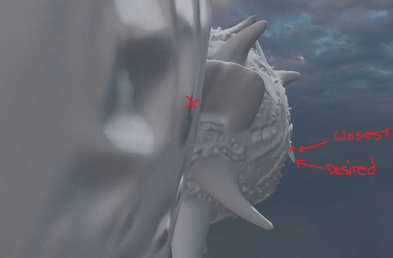
It seems like you would just need to find the nearest point between the high and low poly mesh, and encode the difference in an image. But I see stuff like this in XNormal and it's apparent they have something smarter. How are they calculating these overhangs?
JoeJ
JoeJ

Idk and i have never done this, but i can tell how i would do. The primary ides is using an UV solver, and i don't see a way around that.

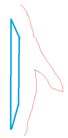
Let's say we have such (red) tooth projected to a low poly (red) quad, shown from the side:

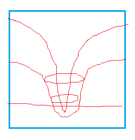
The projection would look like this, having an overlap:

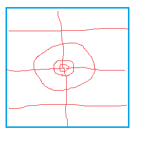
We use an uv solver to smooth it out and removing the overlap. That's exactly what uv solvers do, soy they are perfect for the task:

After that you can obtain 3D positions from the smoothed out parametrization and store offsets in the texture.

However, making a robust uv solver is not easy. A bump like in the example requires to shrink the triangle area much more than elsewhere in the parametrization. So the priority should be preserving angles, preserving areas should be secondary.
When i worked in this 10 years ago, i could not fins a library and had to do it myself.
I ended up with a method of using 'Mean Value Weights'.
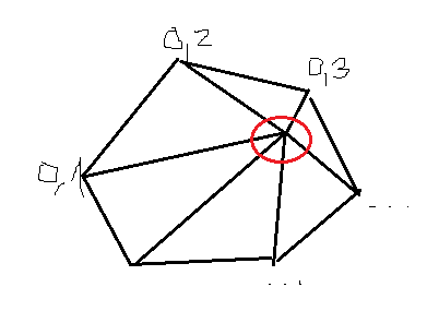
This allows to calculate weights of a vertex ring so you get the vertex in the center (red circle) as the weighted sum of the vertices in the ring ring:

You can calculate the weights from original 3D geometry, then apply them to the flattened parametrization to smooth out the red vertex.
Doing so for all vertices over multiple iterations gives a proper uv solver.

JoeJ
JoeJ

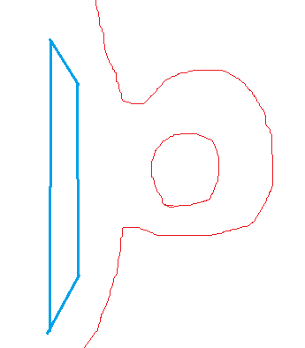
I just thought about a problem with my method. Assuming our tooth does not form a topological bump but a handle with a real hole:

In this case we can not make a bijective parametrization without dividing the handle into multiple charts, and we do not want multiple charts on just one quad of our low poly mesh anyway. (Plus, uv charts usually break displacement mapping because they cause seams.)

So we can only accept overlaps in the parametrization to exist, requiring an uv solver which remains stable and smooth even with overlaps.
It also means that multiple points on the high res 3D mesh can map to the same texture texel, so i would choose the one with the farthest distance, resulting in closing such small holes.

You certainly need to prepare such test cases. I expect this to become very difficult and time consuming!
Ideally there would be some hacky but better way, not requiring parametrization, in further replies...

Otherwise i would consider to settle at 'scalar displacement is good enough'.
The point is, vector displacement means even more artifacts and low quality geometry than scalar displacement, because you will always have less displaced vertices to model the detailed tooth, than you get to model simple flat surfaces where the detail isn't even needed.
Also, i expect you could implement something like Nanite in the same time, avoiding such issues and limitations.

JoeJ
JoeJ

JoeJ wrote:

Ideally there would be some hacky but better way, not requiring parametrization, in further replies...

Yeah, i see the better way now, giving the parametrization as needed without any work. : )

You would just keep the UV from the initial mesh and preserve it while doing the mesh simplification to get the low poly asset.
Which you need to do anyway, i guess.

But then you already have all that's needed. You map the low poly UVs to the high poly UVs which is trivial, then you get the detailed mesh point from those high poly UVs.

So no problem at all.

Topic Locked

This topic has been locked by a moderator. New replies are not allowed.

Sign in to reply to this topic.