(Last modification: August 21st, 2002)
[size="5"]Preface
A few days ago I followed a thread on the Game Developer Algorithms forum. A lot of people exchanged ideas on how the lighting in DOOM III might work. The basis of this discussion was the interview with John Carmack at Beyond3D.
After thinking for myself for some time, I came up with the following example programs. They should show a few basic ideas, that might be useful to create a similar lighting effect as used in DOOM III. Perhaps this might help others to research the lighting algorithm in more detail, after the game is released.
[size="5"]What You Need to Know/Equipment
This will show you variations on diffuse and specular lighting. You will find an extensive explanation of the used diffuse and specular lighting algorithms in the four introductory articles published on www.direct3d.net and www.gamedev.net.
To get a real-time visual experience of the effects shown in the example programs, a modern graphics card is needed, because these programs are using pixel shaders, that are not emulated in software like vertex shaders. Without pixel shaders supported in hardware, the whole graphics pipeline would run in the reference rasterizer.
Check the cap bits in the DirectX caps viewer for support of the proper pixel shader version. Some of the examples require the support of ps.1.1, one example at least ps.1.2 and the last examples requires support for ps.1.4. Additionally you need the newest graphic card driver for those cards.
[bquote]For Geforce 4TI graphics cards, you need a device driver with a higher version number than 30.82 to be able to see the ps.1.2 example running.[/bquote]
[size="5"]What You Are Going To Learn
The target of this article is to show ways how to improve the visual appearance of diffuse and specular reflections on graphic cards with a low level of color precision. Additionally this article will show how to split up an effect into multiple render passes to make it working with a ps.1.1 pixel shader.
The first of the upcoming examples RacorX10 will show you, how to use an illumination map that holds diffuse and specular reflection values. This example additionally uses a gloss map to facilitate a per-pixel specular reflection. To get a point light effect, this example and the other examples use a 2D/1D attenuation map, that should be compatible with all ps.1.1 graphics cards. One of the gotchas this example should show is the usage of multiple passes to achieve the diffuse/specular/point light effect.
The next example called RacorX11 uses additionally a cube normalization map to normalize the light vector, so that the diffuse lighting effect has a higher quality. Whereas RacorX10 only uses two passes to show the lighting effect, this example needs three passes, because of the small number of pixel shader instructions possible in a ps.1.1 shader.
RacorX12 implements all features of RacorX11, but uses a ps.1.2 pixel shader to achieve the same effect. This leads to a reduction of the passes necessary and an improvment of speed.
RacorX13 implements all the features of RacorX11 with a ps.1.4 pixel shader. Compared to RacorX12 this leads to a further reduction of passes. This example creates the same effect that is shown in RacorX11 in only one pass, compared to the three passes used by the latter.
RacorX14 is a vastly improved version of RacorX13, because it uses ps.1.4 specific optimizations, that lead to a reduction of the number of used texture stages and to an improvement of the visual quality. It additionally normalizes the half vector with a cube normalization map.
[size="5"]RacorX10
The first example uses an illumination map, which holds the diffuse and specular values. I got the idea of using an illumination map this way from an article written by Kenneth Hurley [Hurley].
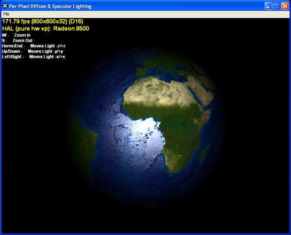
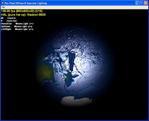
Figure 1 - RacorX 10 - Point Light
His article also helped me a lot in building up the illumination map with Paint Shop Pro. Below are the color and alpha channels of the illumination map:

Figure 2 - Color and Alpha Channel of diffspec.dds
This map stores the diffuse reflection value in the color channel and the specular reflection value in the alpha channel. To get a per-pixel specular reflection, all the following examples use a gloss map stored in the alpha component of the color map:
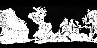
Figure 3 - Specular Values in Alpha Channel of earth.tga
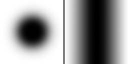
This map can use the whole 8-bit alpha channel to store a range of values, although this screenshot looks like it consists only of a black and white image. The data for the point light is stored in pointlight.dds. This texture stores the function
[font="Courier New"][color="#000080"] f(x, y) = x * x + y * y [/color][/font]
in the color channel and the function
[font="Courier New"][color="#000080"] g(z) = z * z [/color][/font]
in the alpha channel.
Both pictures show that the attenuation values are stored as bidirectional values, because a point light doesn't have a single vector of light like spot lights. The right picture in figure 4 shows the attenuation gradient.
[size="3"]Two Passes
This example needs two passes to execute the necessary vertex and pixel shader values. The first shader pair is responsible for the point light effect (PerPixelPointLight.vsh / PointLight.psh) and the second shader pair is responsible for the diffuse and specular reflection (SpecDot3Pix.vsh / SpecDot3.psh). Below is the relevant source from Render():
// first pass attenuation
 m_pd3dDevice->SetTexture(0, m_pPointLightTexture);
 m_pd3dDevice->SetTexture(1, m_pPointLightTexture);

 // Set the pixel shader
 m_pd3dDevice->SetPixelShader(m_dwPixShaderPointLight);

 // set vertex shader
 m_pd3dDevice->SetVertexShader(m_dwVertShaderPointLight);
 m_pd3dDevice->SetStreamSource( 0, m_pVertices, sizeof(ShaderVertex) );
 m_pd3dDevice->SetIndices(m_pIndexBuffer,0);
 m_pd3dDevice->DrawIndexedPrimitive(D3DPT_TRIANGLELIST,0,m_iNumVertices, 0,
 m_iNumTriangles);

 m_pd3dDevice->SetRenderState(D3DRS_ALPHABLENDENABLE, TRUE);

 // SrcColor * 0 + DestColor * SrcColor
 m_pd3dDevice->SetRenderState(D3DRS_SRCBLEND, D3DBLEND_ZERO);
 m_pd3dDevice->SetRenderState(D3DRS_DESTBLEND, D3DBLEND_SRCCOLOR);

 // second pass
 m_pd3dDevice->SetTexture(0,m_pColorTexture);
 m_pd3dDevice->SetTexture(1,m_pNormalMap);
 m_pd3dDevice->SetTexture(3,m_pIllumMap);

 m_pd3dDevice->SetPixelShader(m_dwPixShaderDot3);
 m_pd3dDevice->SetVertexShader(m_dwVertexSpecular);

 m_pd3dDevice->DrawIndexedPrimitive(D3DPT_TRIANGLELIST,0,m_iNumVertices,0,
 m_iNumTriangles);

m_pd3dDevice->SetRenderState(D3DRS_ALPHABLENDENABLE, FALSE);// SrcColor * 0 + DestColor * SrcColor
m_pd3dDevice->SetRenderState(D3DRS_SRCBLEND, D3DBLEND_ZERO);
m_pd3dDevice->SetRenderState(D3DRS_DESTBLEND, D3DBLEND_SRCCOLOR);[size="3"]First Pass: Point Light Effect
The first shader pair is responsible for the point light effect. You can find a similar implementation of a per-pixel point light in several NVIDIA and ATI examples. Using a point light with an attenuation map is extensively discussed in articles by Sim Dietrich [Dietrich], by Dan Ginsburg/Dave Gosselin [Ginsburg/Gosselin], by Kelly Dempski [Dempski] and others.
Sim Dietrich shows in his article that the following function encoded in an attenuation map delivers good results:
attenuation = 1 - d * d // d = distanceattenuation = 1 - (x * x + y * y + z * z)attenuation = 1 - ((x/r)^2 + (y/r)^2 + (z/r)^2)vs.1.1
; position in clip space
m4x4 oPos, v0, c8
; position in world space
m4x4 r2, v0, c0
; get light vector
add r10, r2, c12
; Divide each component by the range value
mul r10, r10, c33.x
; multiply with 0.5 and add 0.5 to get all values in the range [0..1]
mad r10, r10, c33.yyyy, c33.yyyy
; map the x and y components into the first texture
mov oT0.xy, r10.xy
; z-component v0
mov oT1.x, r10.zps.1.1
tex t0
tex t1
add r0, 1-t0, -t1.a ; (1.0 - t0) - t1.a)[size="3"]Second Pass: Diffuse and Specular Reflection
The pixel shader in the file SpecDot3.psh, that calculates the diffuse and specular reflection with the help of the illumination map and the specular value in the alpha value of the color map looks like this:
ps.1.1
tex t0 ; color map in t0.rgb + gloss map in t0.a
tex t1 ; normal map
texm3x2pad t2, t1_bx2 ; u = t1 dot (t2) light vector
texm3x2tex t3, t1_bx2 ; v = t1 dot (t3) half vector
; fetch texture 4 at u, v
; t3.rgb = (N dot L)
; t3.a = (N dot H)^16
; r0 = (diffuse * color) + ((N dot H)^16 * gloss value)
mul r1.rgb, t3, t0 ; (N dot L) * base texture
+mul r1.a, t0.a, t3.a ; (N dot H)^16 * gloss value
add r0, r1.a, r1This color value from the illumination map has stored the diffuse reflection value in the color channels and the specular reflection value in the alpha channel as shown above in figure 2.
The arithmetic instructions multiply the diffuse reflection value with the color from the color map t0, multiply the specular value from the illumination map with the gloss value from the alpha channel of the color map and add the results from both operations together.
Compared to the pixel shader used in RacorX9, this shader eats up all texture coordinate registers available on ps.1.1 hardware. Unfortunately, the light vector can't be stored in one of the color value registers, because the texm* instruction pair doesn't accept input registers other than texture coordinate registers.
[bquote]There is a much more clever method shown by [Beaudoin/Guardado]. They calculate a specular value by approximating a non-integer power function on a ps.1.1 pixel shader.[/bquote]
Compared to a point light that was calculated in the vertex shader with the dst instruction, the attenuation function used in this example is much simpler, but it works on a per-pixel basis and looks therefore much better. [bquote]This example and the following examples are based on a slightly different framework, than the examples in the Introduction. This is because a precision error in D3DXComputeTangent() showed up, when I normalized the light vector with a cube normalization map. Therefore I use the CreateBasisVectors() and FindAndFixDegenerateVertexBasis() functions from the NVIDIA EffectsBrowser/Cg Browser. You can find them in the file Dot3_Util.cpp. Please check the code comments in LoadXFile() for more info. I have to thank Tim Johnson [Johnson], who pointed me to that problem in the Microsoft DirectX forum.[/bquote]
[size="5"]RacorX11
This example shows, how to use a cube map as a normalization map for the light vector.
Using a cube normalization map helps to prevent the following problem: As light gets closer to the polygon surface, the interpolated light vector will become more and more unnormalized (it will be shortened). The result will be that, as the light approaches the surface, the surface will actually be less illuminated than when the light is further away. The cube normalization map is designed so that, given a texture coordinate representing a 3D vector, the output will always be the normalized vector.
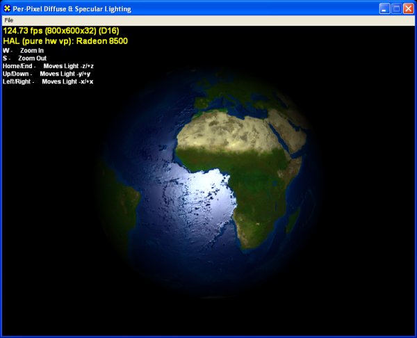
Figure 5 - Light Vector normalized by Cube Normalization Map
Cube maps are made up of 6 square textures of the same size, representing a cube centered at the origin. Each cube face represents a set of directions along each major axis (+x, -x, +y, -y, +z, -z).
The normalization cube map is centered about the origin of the earth object. Each texel on the cube represents a unit light vector, oriented to this origin.

Figure 6 - Cube Map to Normalize Vectors
[bquote]A function that produces a cube normalization map named CreateNormalizationCubeMap() can be found in the NVIDIA EffectsBrowser/Cg Browser source in the file nvtex.cpp.[/bquote]
[size="3"]Three PassesBecause it is not possible to use the diffuse reflection with a light vector normalized by a cube map and the specular reflection in one ps.1.1 pixel shader, all the effects are drawn in three passes onto the object. The first pass uses the cube normalization map to normalize the light vector and calculates the diffuse reflection. The second pass calculates the specular reflection and the third pass draws the point light effect into the frame buffer. This all happens in Render():
// first pass: diffuse(cubemap) * color
m_pd3dDevice->SetRenderState(D3DRS_ALPHABLENDENABLE, TRUE);
// SrcColor * 1 + DestColor * 1
m_pd3dDevice->SetRenderState(D3DRS_SRCBLEND, D3DBLEND_ONE);
m_pd3dDevice->SetRenderState(D3DRS_DESTBLEND, D3DBLEND_ONE);
m_pd3dDevice->SetTexture(0,m_pColorTexture);
m_pd3dDevice->SetTexture(1,m_pNormalMap);
m_pd3dDevice->SetTexture(2,m_pCubeTexture);
m_pd3dDevice->SetPixelShader(m_dwPixShaderDot3);
m_pd3dDevice->SetVertexShader(m_dwVertexSpecular);
m_pd3dDevice->SetStreamSource( 0, m_pVertices, sizeof(ShaderVertex) );
m_pd3dDevice->SetIndices(m_pIndexBuffer,0);
m_pd3dDevice->DrawIndexedPrimitive(D3DPT_TRIANGLELIST, 0, m_iNumVertices, 0,
m_iNumTriangles);
// second pass: specular
m_pd3dDevice->SetTexture(3,m_pIllumMap);
m_pd3dDevice->SetPixelShader(m_dwPixelSpecular);
m_pd3dDevice->DrawIndexedPrimitive(D3DPT_TRIANGLELIST, 0, m_iNumVertices, 0,
m_iNumTriangles);
// third pass: attenuation
// SrcColor * 0 + DestColor * SrcColor
 m_pd3dDevice->SetRenderState(D3DRS_SRCBLEND, D3DBLEND_ZERO);
 m_pd3dDevice->SetRenderState(D3DRS_DESTBLEND, D3DBLEND_SRCCOLOR);
m_pd3dDevice->SetTexture(0, m_pPointLightTexture);
m_pd3dDevice->SetTexture(1, m_pPointLightTexture);
// Set the pixel shader
m_pd3dDevice->SetPixelShader(m_dwPixShaderPointLight);
// set vertex shader
m_pd3dDevice->SetVertexShader(m_dwVertShaderPointLight);
m_pd3dDevice->DrawIndexedPrimitive(D3DPT_TRIANGLELIST, 0, m_iNumVertices, 0,
m_iNumTriangles);
m_pd3dDevice->SetRenderState(D3DRS_ALPHABLENDENABLE, FALSE);To be able to blend together the results of the different passes, alpha blending is used. The following code snippet shows the adding of the first and the second pass:// SrcColor * 1 + DestColor * 1
m_pd3dDevice->SetRenderState(D3DRS_SRCBLEND, D3DBLEND_ONE);
m_pd3dDevice->SetRenderState(D3DRS_DESTBLEND, D3DBLEND_ONE);[size="3"]First Pass: Normalization of Light Vector/Calculation of Diffuse Reflection
The shader pair that uses the cube normalization map and calculates the diffuse reflection effect can be found in diffCubeMap.vsh and diffCubeMap.psh. The pixel shader source is pretty short:
ps.1.1
 tex t0 ; color map
 tex t1 ; normal map
 tex t2 ; cube map

 dp3 r1, t2_bx2, t1_bx2 ; diffuse
mul r0, t0, r1[bquote]Another way to normalize a vector is shown in "Fundamentals of Pixel Shaders". This can be done in the pixel shader with the following code:
dp3 r0, v0_bx2, v0_bx2
mad r0, v0_bias, 1-r0, v0_bx2
Handling normalization this way doesn't burn a texture stage like using a cube normalization map.[/bquote]
Compared to the former example, the diffuse reflection value is the calculated via a dp3 instruction in the pixel shader without using the illumination map. This illumination map is stilled used in the second pass to calculate the specular reflection.dp3 r0, v0_bx2, v0_bx2
mad r0, v0_bias, 1-r0, v0_bx2
Handling normalization this way doesn't burn a texture stage like using a cube normalization map.[/bquote]
[size="3"]Second Pass: Specular Reflection
The pixel shader specular.psh, that is used to calculate the specular reflection is nearly identical to the pixel shader used in RacorX8.
ps.1.1
 tex t0 ; color map + gloss map
 tex t1 ; normal map
 texm3x2pad t2, t1_bx2 ; u = t1 dot (t2) half vector
 texm3x2tex t3, t1_bx2 ; v = t1 dot (t3) half vector
 ; fetch texture 4 at u, v
 ; t3.a = (N dot H)^16
mul r0, t0.a, t3.a ; (N dot H)^16 * gloss valueA more elegant solution is possible by using the texdp3tex instruction together with a 1D specular map, which is shown in the next example.
[size="3"]Third Pass: Point Light Effect
The vertex and pixel shader for the point light effect are the same as in RacorX10.
[size="5"]RacorX12
RacorX12 has only a minor improvement over RacorX11. It uses the ps.1.2 pixel shader instruction texdp3tex.
[bquote]Alload ([email="alload@hotmail.com"]Arnaud Floesser[/email]) sent me an e-mail, in which he pointed me to the idea to use this instruction together with a 2048x1 texture for specular lighting.[/bquote]
This way, we can reduce the number of passes to two. The diffCubeMap.psh and the Specular.psh pairs of RacorX11 are combined into Specular.psh:ps.1.2
tex t0 ; color map + gloss map
tex t1 ; normal map
tex t2 ; cube map
texdp3tex t3, t1_bx2 ; t3.a = (N dot H)^16
dp3 r0, t2_bx2, t1_bx2 ; diffuse
mul r1.rgb, t0, r0 ; diffuse * color
+mul r1.a, t0.a, t3.a ; (N dot H)^16 * gloss value
add r0, r1, r1.aThe 1D texture used for this instruction is build up with the D3DXFillTexture() function provided by the Direct3D utility library:
if (FAILED(D3DXCreateTexture(m_pd3dDevice, 2048, 1, 0, 0, D3DFMT_A8R8G8B8,
 D3DPOOL_MANAGED,&m_pIllumMap)))
 return S_FALSE;

 FLOAT fPower = 16;
 if (FAILED(D3DXFillTexture(m_pIllumMap, LightEval, &fPower)))
return S_FALSE;void LightEval(D3DXVECTOR4 *col,D3DXVECTOR2 *input,
D3DXVECTOR2 *sampSize, void *pfPower)
{
float fPower = (float) pow(input->x,*((float*)pfPower));
col->x = 0;
col->y = 0;
col->z = 0;
col->w = fPower;
}The result is converted by D3DX to whatever format your texture is, since internally this function deals with everything as 32-bit floats, there shouldn't be any precision lose.
[size="5"]RacorX13
The improvement of RacorX13 over RacorX12 is the use of a ps.1.4 pixel shader. With this pixel shader version you can reduce the number of passes to one. This example uses a vertex shader that combines all the functionality used in the two vertex shaders in RacorX12 and a pixel shader that combines all the functionality used in the two pixel shaders in RacorX12.
; t0 - coordinates color map
 ; t1 - light vector
 ; t2 - half vector
 ; t3 - unused
 ; t4 - coordinates 2D attenuation map
 ; t5 - coordinates 1D attenuation map
 ps.1.4
 texld r1, t1 ; cube map
 texld r0, t0 ; normal map
 texcrd r3.rgb, t2 ; half angle vector

 dp3 r1.rgb, r1_bx2, r0_bx2 ; diffuse
 dp3 r4.rgb, r3, r0_bx2 ; specular

 phase

 texld r2, t0 ; color map
 texld r3, r4 ; samples specular value from specular map
 texld r4, t4 ; attenuation 2D map
 texld r5, t5 ; attenuation 1D map
 add r5, 1-r4, -r5.a ; (1.0 - 2Dvalue) - dest

 mul r1.a, r2.a, r3.a ; (N dot H)^16 * gloss value
 +mul r1.rgb, r1, r2 ; diffuse * color
 add r0, r1.a, r1 ; ((N dot H)^16 * gloss value) + (diffuse * color)
mul r0, r0, r5 ; attenuation- Normal map
- Cube normalization map
- Color map
- Illumination Map
- Point light texture
- Point light texture Because of the independence of the texture coordinate data from the texture data in ps.1.4, this pixel shader only uses five texture coordinate registers in the vertex shader. So the texture coordinate register oT3 and the color registers v0 and v1 are still available.
[size="5"]RacorX14
The next example program is an optimized and improved version of RacorX13. The following paragraphs show the different pixel shader interim solutions I had.
My first goal was to free one of the texture stages occupied by the attenuation map. Therefore I fetched the attenuation map in r4 twice:Fetching r4 twice costs an additional mov instruction but reduces the number of used texture stages to five. The newly available sixth stage was used to set the same cube normalization map in r5 to normalize the half vector:; t0 - coordinates color map
; t1 - light vector
; t2 - half vector
; t3 - unused
; t4 - coordinates 2D attenuation map
; t5 - coordinates 1D attenuation map
ps.1.4
texld r1, t1 ; cube map
texld r0, t0 ; normal map
texcrd r3.rgb, t2 ; half angle vector
texld r4, t5 ; attenuation 1D map
dp3 r1.rgb, r1_bx2, r0_bx2 ; diffuse
dp3 r5.rgb, r3, r0_bx2 ; specular
mov r0.r, r4.a
phase
texld r2, t0 ; color map + specular map
texld r3, r5 ; samples specular value from specular map
texld r4, t4 ; attenuation 2D map
add r0, 1-r4, -r0.r ; (1.0 - 2Dvalue) - dest
mul r1.a, r2.a, r3.a ; (N dot H)^16 * gloss value
+mul r1.rgb, r1, r2 ; diffuse * color
add r5, r1.a, r1 ; ((N dot H)^16 * gloss value) + (diffuse * color)
mul r0, r5, r0 ; attenuationThis example program sets the same cube map twice in r1 and r5. The next shader fetches the cube normalization map from one texture stage twice, first with the half vector and later with the light vector:; t0 - coordinates color map
; t1 - light vector
; t2 - half vector
; t3 - unused
; t4 - coordinates 2D attenuation map
; t5 - coordinates 1D attenuation map
ps.1.4
texld r1, t1 ; cube map for light vector
texld r0, t0 ; normal map
texld r5, t2 ; cube map for half angle vector
texld r4, t5 ; attenuation 1D map
dp3 r1.rgb, r1_bx2, r0_bx2 ; diffuse
dp3 r5.rgb, r5, r0_bx2 ; specular
mov r0.r, r4.a
phase
texld r2, t0 ; color map
texld r3, r5 ; samples specular value from specular map
texld r4, t4 ; attenuation 2D map
add r0, 1-r4, -r0.r ; (1.0 - 2Dvalue) - dest
mul r1.a, r2.a, r3.a ; (N dot H)^16 * gloss value
+mul r1.rgb, r1, r2 ; diffuse * color
add r5, r1.a, r1 ; ((N dot H)^16 * gloss value) + (diffuse * color)
mul r0, r5, r0 ; attenuationTo use the same cube map twice, parts of the dp3 instruction for the diffuse reflection had to be moved into the second phase, to be able to re-arrange the temporary registers rn.; t0 - coordinates color map
; t1 - light vector
; t2 - half vector
; t3 - unused
; t4 - coordinates 2D attenuation map
; t5 - coordinates 1D attenuation map
ps.1.4
texld r0, t0 ; normal map
texld r5, t2 ; cube map for half angle vector
texld r4, t5 ; attenuation 1D map
dp3 r5.rgb, r5, r0_bx2 ; specular
mov r1.r, r4.a
phase
texld r2, t0 ; color map
texld r3, r5 ; samples specular value from specular map
texld r4, t4 ; attenuation 2D map
texld r5, t1 ; cube map for light vector
dp3 r5.rgb, r5_bx2, r0_bx2 ; diffuse
add r4, 1-r4, -r1.r ; (1.0 - 2Dvalue) - dest
mul r1.a, r2.a, r3.a ; (N dot H)^16 * gloss value
+mul r1.rgb, r5, r2 ; diffuse * color
add r3, r1.a, r1 ; ((N dot H)^16 * gloss value) + (diffuse * color)
mul r0, r3, r4 ; attenuation
I think RacorX14 produces a better visual appearance than RacorX13, but I cheated a little bit to get the effect. If you take a closer look into the calculation of the first dp3 instruction you can see the cheat.
The cube normalization map returns values from -1..1 and is usually biased and scaled to 0..1 via a _bx2 modifier in the pixel shader. I did not add this modifier to the r5 register in this instruction.
If you add this modifier to this dp3 instruction, you will see an ugly banding effect. This happens because of the low level of color precision of some graphics hardware. Leaving the modifier away distores the result of the dp3 instruction and leads to this nice looking specular effect. A few more elegant solutions to this problem are presented in the paragraph "Improvements" below.[bquote]I haven't tried a -8..8 cube normalization map, possible with ps.1.4 capable graphic cards.[/bquote]
[size="5"]Summarize
This article should have shown you several things. First of all the usage of multiple passes is a well working and efficient solution, that decreases rendering speed nearly linear compared to the number of passes. With this multiple pass approach you can also safely apply multiple overlapping lights without worrying about errors.
If you read the article from back to front, you can see, how to divide a ps.1.4 shader into several ps.1.1 pixel shaders to make it work on a ps.1.1 graphic card. I guess that the knowledge on how to downsize shaders will be even more useful in the future :-).
[size="5"]Further Improvements
There are several ways to improve these examples. I would like to suggest to read the article of Ronald Frazier [Frazier]. He shows a lot of ideas used throughout the examples above and two interesting improvements: First, he adds a self-shadowing term to the light, that sets the light brightness to zero if the light lies behind the polygon. This term additionally helps reducing pixel popping on bump mapped surfaces, when the light is in front of the polygon at a distance between 0 and 0.125 by allowing a linear scaling of the light brightness.
Another interesting idea that I found in this article was an alternative specular formula, which should lead to a smoother specular reflection: 4*((N dot L)^2 - 0.75.
Jakub Klarowicz [Klarowicz] pointed me to an interesting specular lighting formula in the Game Developer Algorithm forum. It is based on R dot V (R- reflected light vector, V - vector to the camera) instead of N dot H and leads to a smoother specular reflection, because it is per-pixel correct. This is because of the way H is calculated and interpolated. It is usually calculated and normalized per vertex, by being derived from V and L, and then renormalized per pixel (as shown for the H vector in the examples above).
A more proper way to get a per-pixel correct vector would be to interpolate it unnormalized and normalize it per pixel later (as shown for the the L vector in the examples above). This might be possible for H with ps.1.4, but requires three normalizations per-pixel. Therefore it is easier to use the unnormalized L and V vectors, normalize them with cube normalization maps and calculate R in the pixel shader and finally R dot V. Jakub Klarowicz has used that in practice and he says that R dot V looks always stable and the highlight is always where it's supposed to be.
A better way to handle specular with per-pixel exponent on fixed-point pixel pipeline, while accounting for the denormalization (due to interpolation) of the half-angle vector, is the "N.H H.H" method discussed in an article in Game Programming Gems III. This technique is used in the OpenGL PointlightShader example available on ATI's web-site and in one of the RenderMonkey examples.
Another good read is the article of David Gosselin [Gosselin], where he shows a way to use three lights in one ps.1.4 pixel shader. I would also like to recommend the article of Steffen Bendel [Bendel] which has an even more innovative approach compared to the examples shown here.
[size="5"]References
[Bendel] Steffen Bendel, "Smooth Lighting with ps.1.4", ShaderX, Wordware Inc., pp ?? - ??, 2002, ISBN 1-55622-041-3
[Beaudoin/Guardado] Philippe Beaudoin , Juan Guardado, "Non-integer Power Function on the Pixel Shader", ShaderX, Wordware Inc., pp. ?? - ??, 2002, ISBN 1-55622-041-3. Available online at Gamasutra.
[Dempski] Kelly Dempski, Real-Time Rendering Tricks and Techniques in DirectX, Premier Press, Inc., pp 578 - 585, 2002, ISBN 1-931841-27-6
[Dietrich] Sim Dietrich, "Attenuation Maps", Game Programming Gems, Charles River Media Inc., pp 543 - 548 2000, ISBN 1-58450-049-2
[Frazier] Ronald Frazier, "Advanced Real-Time Per-Pixel Lighting in OpenGL", http://www.ronfrazie...l_lighting.html
[Ginsburg/Gosselin] Dan Ginsburg/Dave Gosselin, "Dynamic Per-Pixel Lighting Techniques", Game Programming Gems 2, Charles River Media Inc., pp 452 - 462, 2001, ISBN 1-58450-054-9
[Gosselin] David Gosselin, "Character Animation with Direct3D Vertex Shaders", ShaderX, Wordware Inc., pp ?? - ??, 2002, ISBN 1-55622-041-3.
[Hurley] Kenneth Hurley, "Photo Realistic Faces with Vertex and Pixel Shaders", ShaderX, Wordware Inc., pp ?? - ??, 2002, ISBN 1-55622-041-3
[Johnson] Tim Johnson, Message in Microsoft DirectX forum.
[Klarowicz] Jakub Klarowicz, Message in Game Developer Algorithm forum.
[size="5"]Acknowledgements
I would like to thank the following individuals for proof-reading and helping me to improve this article:- Arnaud Floesser
- Damian Trebilco (Auran)
(C) 2002 [email="wolf@direct3d.net"]Wolfgang Engel[/email], Frankenthal, Germany


