Inspiration
The game Objects in Space has been demoing their game at shows such as PAX with a giant space-ship cockpit controller, complete with light-up buttons, analog gauges, LED status indicators, switches, etc... It adds a lot to the immersion when playing the game:

They have an Arduino tutorial over on their site, and a description of a communication protocol for these kinds of controllers.
I want to do the same thing for my game ?
For this example, I'm going to spend ~$40 to add some nice, big, heavy switches to my sim-racing cockpit. The main cost involved is actually these switches themselves -- using simple switches/buttons could halve the price! They're real hardware designed to withstand 240W of power, and I'll only be putting 0.03W or so through them.
Also, as a word of warning, I am a cheapskate, so I'm linking to the cheap Chinese website where I buy lots of components / tools. One of the downsides of buying components on the cheap is that they often don't come with any documentation, so I'll deal with that issue below, too

Main components
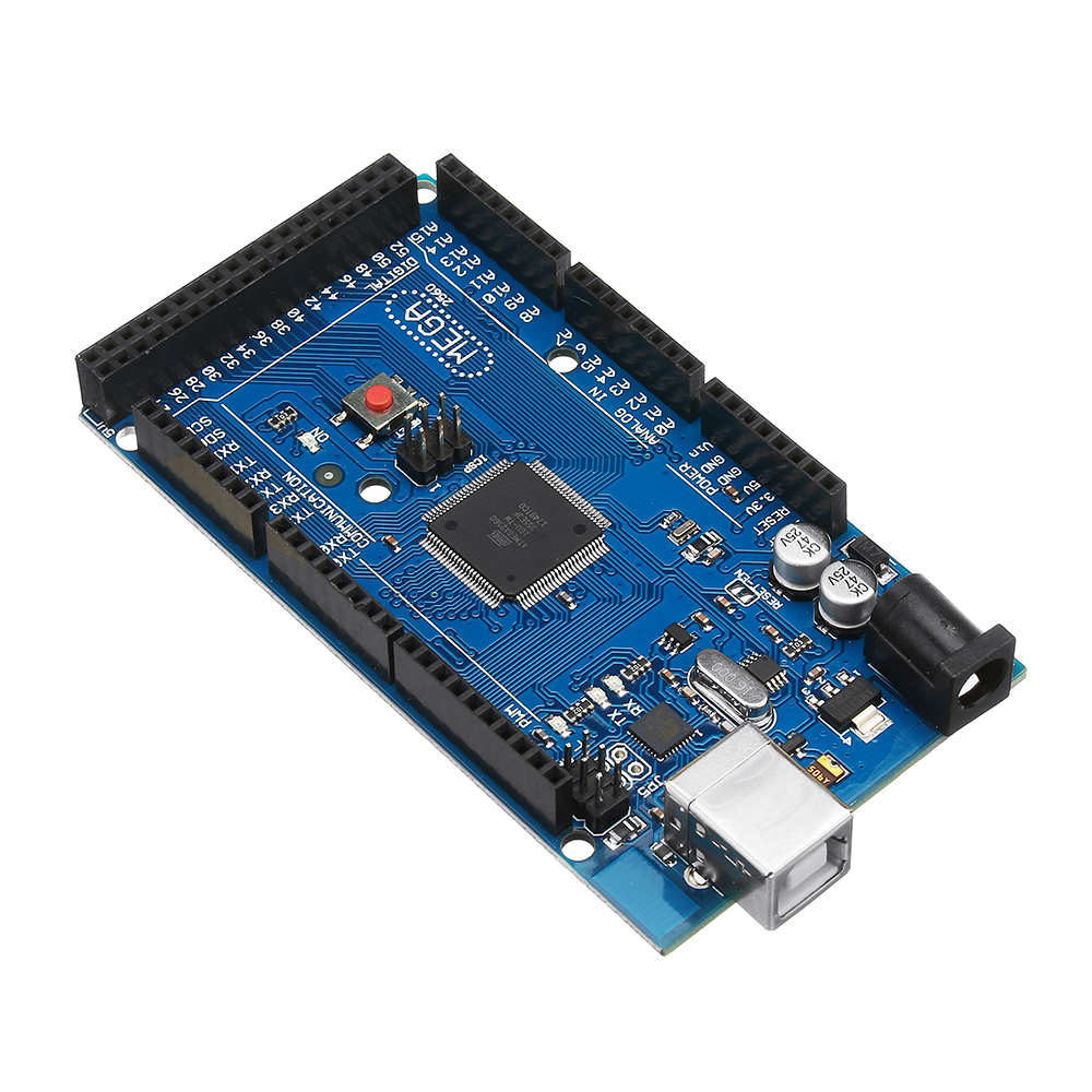
- Arduino Mega2560 - $9
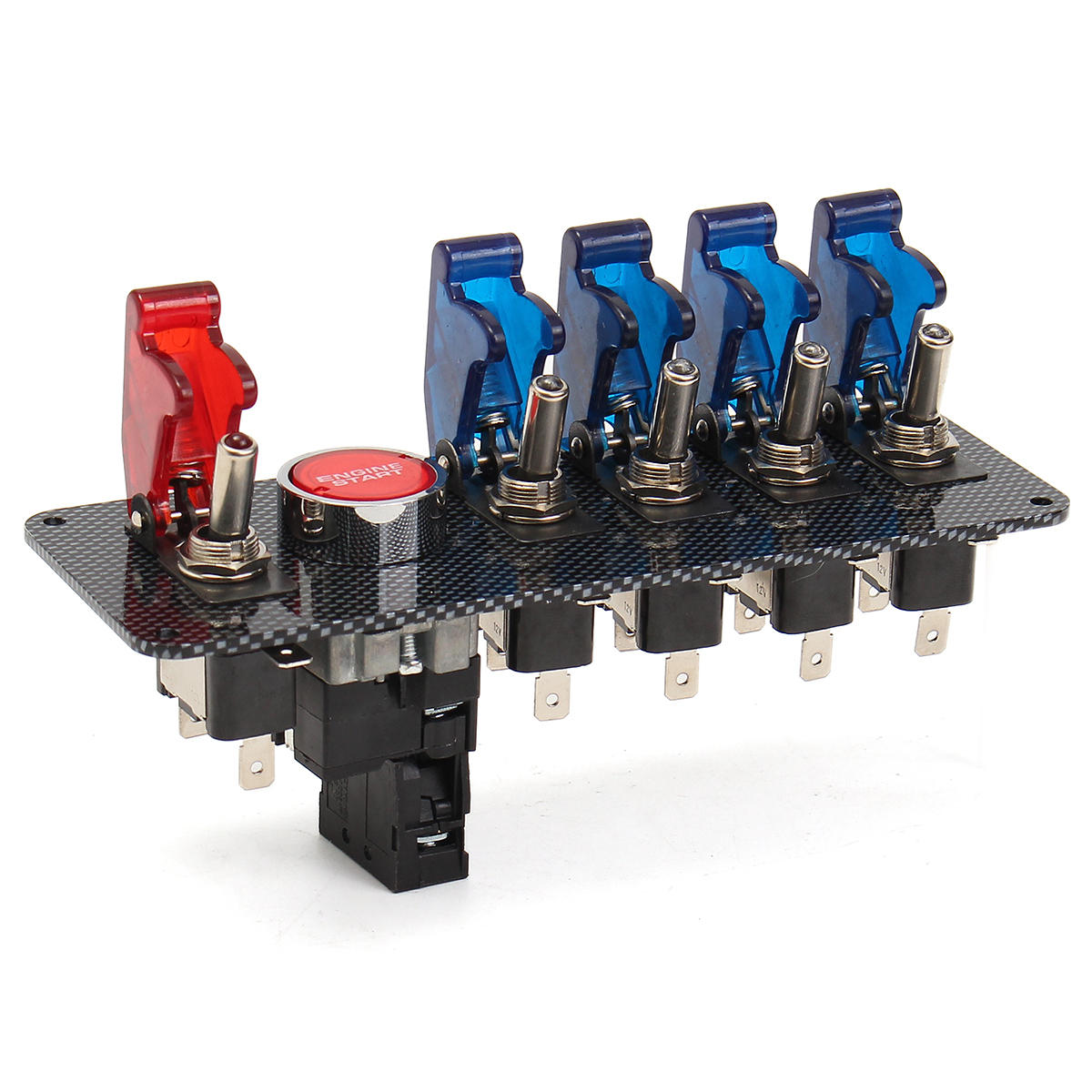
- Racing ignition switch panel - $26
- A pile of jump wire (male to male, male to female, etc...) - $2
+
+
.JPG)
Recommended Tools
- A soldering iron (a good one is worth it, but a cheap one from your hardware store will do)
- Solder (60/40 lead rosin core is easy to work with, though bad for the environment...)
- Heat shrink (and a hot air gun, hair dryer, or cigarette lighter) or electrical tape
- A hot glue gun (and glue sticks), or some epoxy resin
- A multimeter
- Wire cutters / stripper, or a pair of scissors if you're cheap.
Software
- Arduino IDE for programming the main Arduino CPU
- For making a controller that appears as a real hardware USB gamepad/joystick:
- FLIP for flashing new firmware onto the Arduino's USB controller
- The arduino-usb library on github
- For making a controller that your game talks to directly (or appears as a virtual USB gamepad/joystick?
- My ois_protocol library on github
- The vJoy driver, if you want to use it as a virtual USB gamepad/joystick.
Disclaimer
I took electronics in high school and learned how to use a soldering iron, and that you should connected red wires to red wires, and black wires to black wires... Volts, amps and resistance have an equation that relates them? That's about the extent of my formal electronics education

This has been a learning project for me, so there may be bad advice or mistakes in here! Please post in the comments.
Part 1, making the thing!
Dealing with undocumented switches...
As mentioned above, I'm buying cheap parts from a low-margin retailer, so my first job is figuring out how these switches/buttons work.
A simple two-connector button/switch
The button is easy, as it doesn't have any LEDs in it and just has two connectors. Switch the multimeter to continuity mode (

) and touch one probe to each of the connectors -- the screen will display OL (open loop), meaning there is no connection between the two probes. Then push the button down while the probes are still touching the connectors -- the screen will display something like 0.1Ω and the multimeter will start beeping (indicating there is now a very low resistance connection between the probes -- a closed circuit).
Now we know that when the button is pressed, it's a closed circuit, and otherwise it's an open circuit. Or diagrammatically, just a simple switch:

Connecting a switch to the Arduino
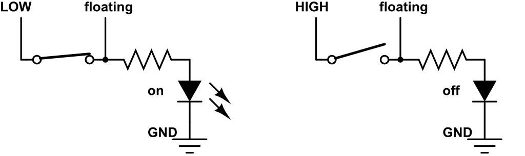
Find two pins on the Arduino board, one labelled GND, and one labelled "2" (or any other arbitrary number -- these are general purpose IO pins that we can control from software).
If we connect our switch like this and then tell the Arduino to configure pin "2" to be an INPUT pin, we get the circuit on the left (below). When the button is pressed, pin 2 will be directly connected to ground / 0V, and when not pressed, pin 2 will not be connected to anything. This state (not connected to anything) is called "floating", and unfortunately it's not a very good state for our purposes. When we read from the pin in our software (with digitalRead(2)) we will get LOW if the pin is grounded, and an unpredictable result of either LOW or HIGH if the pin is in the floating state!
To fix this, we can configure the pin to be in the INPUT_PULLUP mode, which connects a resistor inside the processor and produces the circuit on the right. In this circuit, when the switch is open, our pin 2 has a path to +5V, so will reliably read HIGH when tested. When the switch is closed, the pin still has that high-resistance path to +5V, but also has a no-resistance path to ground / 0V, which "wins", causing the pin to read LOW.
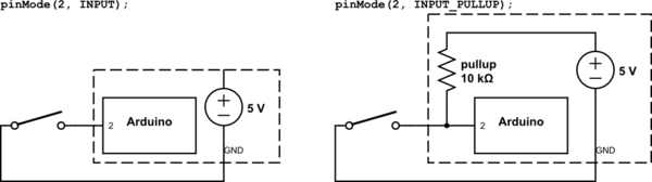
This might feel a little backwards to software developers -- pushing a button causes it to read false / LOW, and when not pressed it reads true / HIGH
We could do the opposite, but the processor only has in-built pull-up resistors and no in-built pull-down resistors, so we'll stick with this model.
The simplest Arduino program that reads this switch and tells your PC what state it's in looks something like below. You can click the upload button in the Arduino IDE and then open the Serial Monitor (in the Tools menu) to see the results.
void setup() { Serial.begin(9600); pinMode(2, INPUT_PULLUP); } void loop() { int state = digitalRead(pin); Serial.println( state == HIGH ? "Released" : "Pressed" ); delay(100);//artifically reduce the loop rate so the output is at a human readable rate... }
More semi-documented switches...
An LED switch with three connectors
The main switches on my panel thankfully have some markings on the side labeling the three connectors:

I'm still not 100% certain how it works though, so again, we get out the multimeter in continuity mode and touch all the pairs of connectors with the switch both on and off... however, this time, the multimeter doesn't beep at all when we put the probes on [GND] and [+] with the switch "on"! The only configuration where the multimeter beeps (detects continuity) is when the switch is "on" and the probes are on [+] and [lamp].
The LED within the switch will block the continuity measurement, so from the above test, we can guess that the LED is connected directly to the [GND] connector, and not the [+] or [lamp] connectors. Next, we can put the multimeter onto diode testing mode (

symbol) and test the pairs of connectors again - but this time polarity matters (red vs black probe). Now, when we put the red probe on [lamp] and the black probe on [GND], the LED lights up and the multimeter reads 2.25V. This is the forward voltage of the diode, or the minimum voltage required to make it light up. Regardless of switch position, 2.25V from [lamp] to [GND] causes the LED to come on. When we put the red probe on [+] and the black probe on [GND] the LED only comes on if the switch is also on.
From these readings, we can guess that the internals of this switch looks something like below, reproducing our observations:
- [+] and [lamp] short circuit when the switch is on / closed.
- A positive voltage from [lamp] to [GND] always illuminates the LED.
- A positive voltage from [+] to [GND] illuminates the LED only when the switch is on / closed.
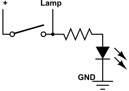
Honestly the presence of the resistor in there is a bit of a guess. LED's need to be paired with an appropriate resistor to limit the current fed into them, or they'll burn out. Mine haven't burned out, seem to be working correctly, and I found a forum post on the seller's website saying there was an appropriate resistor installed for 12V usage, so this saves me the hassle of trying to guess/calculate the appropriate resistor to use here
Connecting this switch to the Arduino
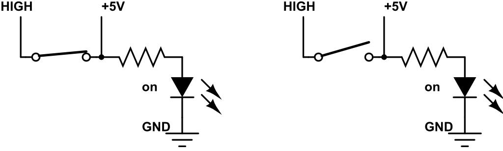
The simplest way to use this on the Arduino is to ignore the [lamp] connector, connect [GND] to GND on the Arduino, and connect [+] to one of the Arduino's numbered pins, e.g. pin 3.
If we set pin 3 up as INPUT_PULLUP (as with the previous button) then we'll end up with the result below. The top left shows the value that we will recieve with "digitalRead(3)" in our Arduino code.
When the switch is on/closed, we read LOW and the LED will illuminate! To use this kind of switch in this configuration you can use the same Arduino code as in the button example.
Problems with this solution
Connected to the Arduino, the full circuit looks like:
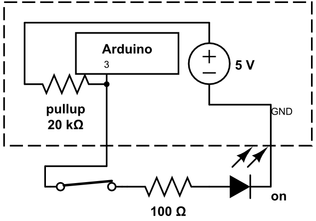
Here, we can see though, that when the switch is closed, instead of there being quite a small current-limiting resistor in front of the LED (I'm guessing 100Ω here), there is also the 20kΩ pullup resistor which will further reduce the amount of current that can flow through the LED. This means that while this circuit works, the LED will not be very bright.
Another downside with this circuit is we don't have programmatic control over the LED - it's on when the switch is on, and off when the switch is off.
We can see what happens if we connect the [lamp] connector to either 0V or +5V below.
When [lamp] is connected to 0V, the LED is permanently off (regardless of switch position), and the Arduino position sensing still behaves. This gives us a nice way of programatically disabling the LED if we want to!
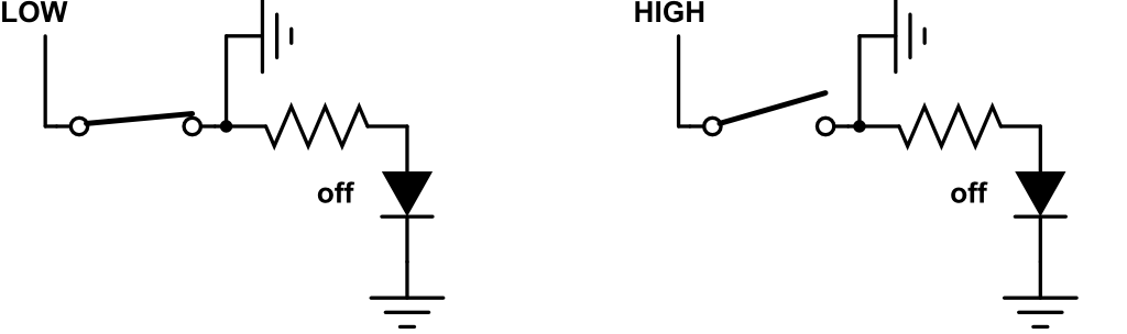
When [lamp] is connected to +5V, the LED is permanently on (regardless of switch position), however, the Arduino position sensing is broken - our pin will always read HIGH

Connecting this switch to the Arduino properly
We can overcome the limitations described about (low current / LED intensity, and no LED programmatic control) by writing a bit more software! To resolve the conflict between being able to control the LED and our position sensing getting broken by LED control, we can time-slice the two -- i.e. temporarily turn off the LED when reading the sensor pin (#3).
First, connect the [lamp] pin to another general purpose Arduino pin, e.g. 4, so we can control the lamp.
To make a program that reads the switch position reliably and also controls the LED (we'll make it blink here) we just have to be sure to turn the LED off before reading the switch state. Hopefully the LED will only be disabled for a fraction of a millisecond, so it shouldn't be a noticeable flicker:
int pinSwitch = 3; int pinLed = 4; void setup() { //connect to the PC Serial.begin(9600); //connect our switch's [+] connector to a digital sensor, and to +5V through a large resistor pinMode(pinSwitch, INPUT_PULLUP); //connect our switch's [lamp] connector to 0V or +5V directly pinMode(pinLed, OUTPUT); } void loop() { int lampOn = (millis()>>8)&1;//make a variable that alternates between 0 and 1 over time digitalWrite(pinLed, LOW);//connect our [lamp] to +0V so the read is clean int state = digitalRead(pinSwitch); if( lampOn ) digitalWrite(pinLed, HIGH);//connect our [lamp] to +5V Serial.println(state);//report the switch state to the PC }
On the Arduino Mega, pins 2-13 and 44-46 can use the analogWrite function, which doesn't actually produce voltages between 0V and +5V, but approximates them with a square wave. You can use this to control the brightness of your LED if you like! This code will make the light pulse from off to on instead of just blinking:
void loop() { int lampState = (millis()>>1)&0xFF;//make a variable that alternates between 0 and 255 over time digitalWrite(pinLed, LOW);//connect our [lamp] to +0V so the read is clean int state = digitalRead(pinSwitch); if( lampState > 0 ) analogWrite(pinLed, lampState); }
Assembly tips
This post is already big enough so I won't add a soldering tutorial on top, I'll leave that to google!
However, some basic tips:
- When joining wires to large metal connectors, do make sure that your iron is hot first, and take a moment to also heat up the metal connector too. The point of soldering is to form a permanent bond by creating an alloy, but if only one part of the connection is hot, you can easily end up with a "cold joint", which superficially looks like a connection, but hasn't actually bonded.
- When joining two wires together, make sure to slip a bit of heat-shrink onto one of them first - you can't slip the heat-shrink on after the joint is made. This sounds obvious, but I'm always forgetting to do so and having to fall back to using electrical tape instead of heat-shrink... Also, slip the heat-shrink far away from the joint so it doesn't heat up prematurely. After testing your soldered connection, slide the heat-shrink over the joint and heat it up.
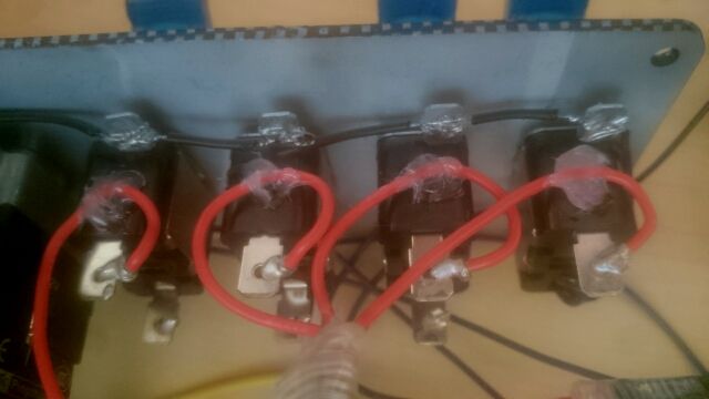
- The thin little dupont / jump wire that I listed at the start are great for solderless connections (e.g. plugging into the Arduino!) but are quite fragile. After soldering these, use hot glue to hold them in place and move any strains away from the joint itself. e.g. the red wires below might get pulled on while I'm working on this, so after soldering them to the switches, I've fixed them in place with a dab of hot glue:
Part 2, make it act as a game controller!
To make it appear as a USB game controller in your OS, the code is quite simple, but unfortunately we also have to replace the firmware on the Arduino's USB chip with a custom one that you can grab from here: https://github.com/harlequin-tech/arduino-usb
Unfortunately, once you put this custom firmware on your Arduino, it is now a USB-joystick, not an Arduino any more
So in order to reprogram it, you have to again re-flash it with the original Arduino firmware. Iterating is a bit of a pain -- upload arduino code, flash joystick firmware, test, flash arduino firmware, repeat...
An example of an Arduino program for use with this firmware is below -- it sets up three buttons as inputs, reads their values, copies it into the data structure expected by this custom firmware, and send the data. Rinse and repeat.
// define DEBUG if you want to inspect the output in the Serial Monitor // don't define DEBUG if you're ready to use the custom firmware #define DEBUG //Say we've got three buttons, connected to GND and pins 2/3/4 int pinButton1 = 2; int pinButton2 = 3; int pinButton3 = 4; void setup() { //configure our button's pins properly pinMode(pinButton1, INPUT_PULLUP); pinMode(pinButton2, INPUT_PULLUP); pinMode(pinButton3, INPUT_PULLUP); #if defined DEBUG Serial.begin(9600); #else Serial.begin(115200);//The data rate expected by the custom USB firmware delay(200); #endif } //The structure expected by the custom USB firmware #define NUM_BUTTONS 40 #define NUM_AXES 8 // 8 axes, X, Y, Z, etc typedef struct joyReport_t { int16_t axis[NUM_AXES]; uint8_t button[(NUM_BUTTONS+7)/8]; // 8 buttons per byte } joyReport_t; void sendJoyReport(struct joyReport_t *report) { #ifndef DEBUG Serial.write((uint8_t *)report, sizeof(joyReport_t));//send our data to the custom USB firmware #else // dump human readable output for debugging for (uint8_t ind=0; ind<NUM_AXES; ind++) { Serial.print("axis["); Serial.print(ind); Serial.print("]= "); Serial.print(report->axis[ind]); Serial.print(" "); } Serial.println(); for (uint8_t ind=0; ind<NUM_BUTTONS/8; ind++) { Serial.print("button["); Serial.print(ind); Serial.print("]= "); Serial.print(report->button[ind], HEX); Serial.print(" "); } Serial.println(); #endif } joyReport_t joyReport = {}; void loop() { //check if our buttons are pressed: bool button1 = LOW == digitalRead( pinButton1 ); bool button2 = LOW == digitalRead( pinButton2 ); bool button3 = LOW == digitalRead( pinButton3 ); //write the data into the structure joyReport.button[0] = (button1?0x01:0) | (button2?0x02:0) | (button3?0x03:0); //send it to the firmware sendJoyReport(joyReport) }
Part 3, integrate it with YOUR game!
As an alternative the the above firmware hacking, if you're in control of the game that you want your device to communicate with, then you can just talk to your controller directly -- no need to make it appear as a Joystick to the OS! At the start of this post I mentioned Objects In Space; this is exactly the approach that they used. They developed a simple ASCII communication protocol that can be used to allow your controller and your game to talk to each other. All you have to do is enumerate the serial ports on your system (A.K.A. COM ports on Windows, and btw look how awful this is in C), find the one with a device named "Arduino" connected to it, open that port and start reading/writing ASCII to that handle. On the Arduino side, you just keep using the Serial.print functions that I've used in the examples so far.
At the start of this post, I also mentioned my library for solving this problem: https://github.com/hodgman/ois_protocol
This contains C++ code that you can integrate into your game to act as the "server", and Arduino code that you can run on your controller to act as the "client".
Setting up your Arduino
In example_hardware.h I've made classes to abstract the individual buttons / switches that I'm using. e.g. `Switch` is a simple button as in the first example, and `LedSwitch2Pin` is the controllable LED switch from my second example.
The actual example code for my button panel is in example.ino.
As a smaller example, let's say we have a single button to be sent to the game, and a single LED controlled by the game. The required Arduino code looks like:
#include "ois_protocol.h" //instantiate the library OisState ois; //inputs are values that the game will send to the controller struct { OisNumericInput myLedInput{"Lamp", Number}; } inputs; //outputs are values the controller will send to the game struct { OisNumericOutput myButtonOutput{"Button", Boolean}; } outputs; //commands are named events that the controller will send to the game struct { OisCommand quitCommand{"Quit"}; } commands; int pinButton = 2; int pinLed = 3; void setup() { ois_setup_structs(ois, "My Controller", 1337, 42, commands, inputs, outputs); pinMode(pinButton, INPUT_PULLUP); pinMode(pinLed, OUTPUT); } void loop() { //read our button, send it to the game: bool buttonPressed = LOW == digitalRead(pin); ois_set(ois, outputs.myButtonOutput, buttonPressed); //read the LED value from the game, write it to the LED pin: analogWrite(pinLed, inputs.myLedInput.value); //example command / event: if( millis() > 60 * 1000 )//if 60 seconds has passed, tell the game to quit ois_execute(ois, commands.quitCommand); //run the library code (communicates with the game) ois_loop(ois); }
Setting up your Game
The game code is written in the "single header" style. Include oisdevice.h into your game to import the library.
In a single CPP file, before #including the header, #define OIS_DEVICE_IMPL and #define OIS_SERIALPORT_IMPL -- this will add the source code for the classes into your CPP file. If you have your own assertions, logging, strings or vectors, there are several other OIS_* macros that can be defined before importing the header, in order to get it to use your engine's facilities.
To enumerate the COM ports and create a connection for a particular device, you can use some code such as this:
OIS_PORT_LIST portList; OIS_STRING_BUILDER sb; SerialPort::EnumerateSerialPorts(portList, sb, -1); for( auto it = portList.begin(); it != portList.end(); ++it ) { std::string label = it->name + '(' + it->path + ')'; if( /*device selection choice*/ ) { int gameVersion = 1; OisDevice* device = new OisDevice(it->id, it->path, it->name, gameVersion, "Game Title"); ... } }
Once you have an OisDevice instance, you should call its Poll member function regularly (e.g. every frame), you can retrieve the current state of the controller's output with DeviceOutputs(), can consume events from the device with PopEvents() and can send values to the device with SetInput().
An example application that does all of this is available at example_ois2vjoy/main.cpp
Part 4, what if you wanted part 2 and 3 at the same time!?
To make your controller work in other games (part 2) we had to install custom firmware and one Arduino program, but to make the controller fully programmable by your game, we used standard Arduino firmware and a different Arduino program. What if we want both at once?
Well, the example application that is linked to above, ois2vjoy, solves this problem
This application talks to your OIS device (the program from Part 3) and then, on your PC, converts that data into regular gamepad/joystick data, which is then sent to a virtual gamepad/joystick device. This means you can leave your custom controller using the OIS library all the time (no custom firmware required), and when you want to use it as a regular gamepad/joystick, you just run the ois2vjoy application on your PC, which does the translation for you.
Part 5, wrap up
I hope this was useful or interesting to some of you. Thanks for making it to the end!
If this does tickle you fancy, please consider collaborating / contributing to the ois_protocol library! I think it would be great to make a single protocol to support all kinds of custom controllers in games, and encourage more games to directly support custom controllers!


This is mind blowing! Very cool!!!") Thanks for sharing!
Thanks for sharing!