
Intro to 3D Graphics Programming: Volume IV
Begins the discussion of polygon fillers with flat and Lambert lighting.
Hi again! :-)
Well, it looks like we're done with the beginning 3D info, so it's time to take a break for a few weeks and change gears to something that people seem to be very interested in. You know 'em, you love 'em, and you love to hate 'em....
Polygon fillers.
Or perhaps I should call them "shading algorithms"... well, not all of them are shading (f.ex. texture mapping), so "polygon fillers" is probably the better term. Anyway, the fillers I'm going to cover over time are ones we seem to see quite a bit of these days...
- Flat/Lambert Shading (today's article! Yippee!
- Gouraud Shading
- Phong and Interpolated Phong Shading
- Affine Texture Mapping
- Perspective Texture Mapping
- Environment Mapping (better called Reflection Mapping) There will be other articles in between all of these; for example, I've decided to move up the discussion of BSP trees to the NEXT ARTICLE, #5, up from what would have been #10 or so. This is because you can't do solid objects without some kind of face ordering, and the three generic options seem to be sorting (painter's algorithm), Z-buffering, and BSP trees.
Since I hate sorting... I mean REALLY hate sorting, and Z-buffering is just a pain in the neck, BSP trees seem to be a pretty important thing to discuss early on. So I'm doing them for the next article. After that, we'll be going up through Phong before I do some other stuff before texture mapping. This week's article is going to cover Flat Shading (shading an entire poly with one color), and Lambert Shading (same as flat shading, but that the one color is chosen by a lightsource).
Hope you're prepared. :-)
Before we begin, I've got to point out two things...
One, the example source for article #3, (i.e. what would be DN3D_3.ZIP). After thinking about it, sample source just to demonstrate normals without reason is pretty asinine. It would make more sense to actually have a USE for those normals. As such, I'm going to concentrate the example source for both article #3 and this one, #4, into a single supplement, DN3D_3&4. This will allow me to actually have a purpose for the normals I explained last time, using them for solid objects.
[size="5"] Flat Filling - What's Involved?
Just like everything else, there are many ways to do flat filling. The two methods I see most commonly seem to be...
- Dual Edge Fill - Start at the top of your polygon and work downward simultaneously along both the left and right edges, changing lines when vertices are hit on either side, and stop when both traces hit the final vertex. Fill as you go.
- Single Edge Buffered Fill - Draw lines along each edge, not plotting the pixels but saving their offsets. Fill in an edge buffer appropriately. After all the sides are processed, use the edge buffer for the fill.
Note that I just made up the names; if there are actual names for these methods then substitute those in there instead. - Replace the part (or line of code) where the pixel is drawn to a section that checks the current offset against the left/right offsets of the current Y line and updates if necessary.
- When the Y changes (in the major for Y-biased lines (abs(slope) > 1) and in the minor for X-biased lines (abs(slope) < 1) ), update the current Y line in the buffer so you know which left/right offsets to check against. The first Y will be the Y value from the first point, at the start of the line. That's all it is! If you do this for all of your edges of your polygon, you'll have a buffer that's ready for filling.
But wait! What about when we first start the edge tracing? What do we do if there are no offsets to check against? Are there any "initial" values that we need?
Yup, sure are. Before each poly fill, you need to refill the buffer with initial values. You can either refill the entire buffer, or as an optimization you can just refill the buffer just for the Y lines that the previous poly changed. Either way, you want to guarantee that when a trace is the first one to hit a given Y line, it is absolutely certain it WILL be the rightmost and WILL be the leftmost offset. What values to use then? Simple... use your maximum value (either FFFFh or FFFFFFFFh) for the leftmost offset, and minimum value (0) for the rightmost. There's not a single line that will go down that won't replace those.
Anyway, now you've got this nice filled buffer for your polygon. Now we just gotta fill between the edges. Simple enough. For each line that the edge traces have filled in, you just start at the left offset, and fill (rightoffset-leftoffset) pixels in. In assembly, this is a simple thing to do in a linear screen layout, like Mode 13h (or a blitted linear virtual screen)...
You could also divide the length by 4 and use stosd, then fill in the remaining bytes after, like so...mov edi, leftoffset
mov ecx, rightoffset
sub ecx, edi
mov al, color
cld
rep stosb
Something like that. There are variations and optimizations all over the place, and I'll leave those to you to figure out. :-)mov edi, leftoffset
mov ecx, rightoffset
sub ecx, edi
mov ebx, ecx
shr ecx, 2
mov eax, color ; assuming color is already prepared to be in all 4 bytes.
cld
rep stosd
mov ecx, ebx
and ecx, 3
rep stosb
The only thing left that the filler needs to know is exactly WHICH scanlines are the ones that need to be filled, i.e., where's the top and bottom of the fill process? Well you've got several options. One would be to sort your vertices by Y before the fill process begins, and fill from the Y of the top one to the Y of the bottom one (this is very very easy for polys with low numbers of sides, like triangles). You can also do a tremendously slow method that checks the offset buffer each line for the values and ignores the line if both the left is the maximum value and the right is the minimum value, like the initialization gave it. That's another option. It's very inefficient unless you have polys with really high numbers of sides, but that's extremely rare (and in my opinion kinda dumb But nonetheless, it's an option.... there are lots of ways to accomplish each step.
And that's it! Our flat filler is done... pretty simple, eh? This is one of those routines that people seem to think is a lot harder than it actually is, until you just get right down to it and code the sucker (note that that's with this method... I still believe that first method is damn difficult in all honesty... I doubt I'll ever break down and code it that way :-)
Okay, so we can do flat filling. Well what if we want to lightsource that color? That's when our normals come into play...
[size="5"]Turning Your Flat-filler Into A Lambert-filler
The whole idea behind lightsourcing a color is pretty simple... find the angle between the surface and the lightsource (assumed to be a point somewhere), and shade appropriately. The narrower the angle (closest to zero), the more the surface points towards the light and the brighter it gets. The greater the angle (approaching 90 degrees), the more the surface gets darker and darker. Finally, between 90 and 180 degrees, the surface is pointing AWAY from the direction of the light and gets a "shadow" color, which is either the ambient light color (the minimum) or pure black if there's no ambient light (which can create some pretty cool effects actually).
So all we have to figure out is, how do we find the angle between the direction of the surface and the lightsource? Here come our normals...
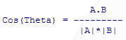
We already know from last time that our normal is the direction the surface is "pointing" towards. Well we can find the angle "between" two vectors, using that thing we ignored the last time, the Dot Product... recall that the Dot Product
Well the cosine of the angle Theta between the two vectors A and B isA.B = (Ax * Bx) + (Ay * By) + (Az * Bz)

where |A| and |B| are the lengths of vectors A and B, respectively.
Now we know that vector A is going to be our normal, so what's vector B? We need some kind of location for the lightsource, and that's what B is for. Our normal A is a vector from the origin, so if we make a second vector from the origin to the light by "moving" the position of the lightsource appropriately to preserve the same angle with the polygon, we'll get the B vector that we need.
Well there's a problem here... in order to move (translate) the lightsource to be relative to the origin, we need to know where our relative origin is, i.e. what point on the polygon is our theoretical "new" origin?
The point you use for the relative origin will determine exactly where the lightsource vector comes from, and will directly affect the final color. Now if you just use one of the vertices, you'll get a major accuracy problem. Take a cube for example... if one of the faces of the cube is pointed directly at the lightsource, you still won't get the brightest possible color if you use a vertex for checking, because even though the FACE is pointed right at the light, the normal AT THAT VERTEX is certainly not. It's parallel to the direction of the plane, but at a different place, which will give a different angle to the light.
So what point should we use? Well if we think about it, we want the light to be judged by the most average point on the polygon, since that will give the best representation of what the color SHOULD be. What's the most average point on the polygon? Why the center, of course. Just average the coordinates of all the vertices on the poly (for each component), and the final coordinate should be right in the dead center of your surface. This is a new vertex which otherwise is meaningless as far as the model goes, but it's perfect to use for lightsourcing.
Note, if this whole lightsourcing section has confused you to death (quite likely with the way I talk then don't fret... I'll put a PCX diagram in the supplement to clarify what I'm talking about in here.
Now what about that "length" deal? We need to take the Dot Product of A and B, but then we need to divide by the length A * length B in order to get our angle cosine. The thing is, divides aren't cool.
You might be realizing now why we set our normals to length 1 back in the last article. This is why.
So which one of these two methods is better? Well it depends. I've heard from people that the first method is faster (debatable), but that's IF you get it to work. The problem with the first method is that there are so many conditions (like when vertices are hit along the edge, trying to update correctly without loosing track of which side is where, and problems with straight horizontal edges), that it becomes a big problem for debugging.
I recall trying that first method when I first wanted to make a poly filler. It failed miserably, even after weeks of trying to debug it. Nonetheless, if you get it to work, it's reportedly quite fast. I can't confirm this myself, as I abandoned the algorithm.
The second method, on the other hand, is quite easy to implement, and still quite fast from my point of view. It also has the advantage of working for any-number-of-sided polygons, just by pasting in a few more edge traces for the new edges; the algo stays the same. The versatility and ease of coding are big advantages for it, and fortunately there are no special conditions to worry about, which helps in speed quite a bit...
As you can probably tell, I'll be covering the second method in this article. ;-)
[size="5"]Overview of the Edge Buffered Fill
The fill basically has two very distinct parts. The first is the edge buffering, and the second is the filler itself.
You need to set up a memory buffer that has room for two offsets for each Y line on the screen (in whatever resolution you use). The two offsets total either 4 bytes for real mode, or 8 bytes for protected mode. Multiply that amount by your Y resolution, and that's your buffer size.
All we need to do is fill in this buffer with the left and right sides of the polygon for each scanline, and then the filler will just start at the left and fill to the right for each. No biggie.
So how do we fill in this buffer? Well what we need is a special routine that "traces" a given edge and fills in the buffer as it goes along, checking each line to see where's it's at to know if the buffer needs to be updated. If the current offset is less than the leftmost offset at the current scanline, it replaces the left offset with itself. The same goes for the right offset.... if the current one is greater, it replaces the right offset with itself. This goes on until the edge trace is done. If you do this for all the edges of the polygon (3 for triangle, 4 for quadrilateral, etc.), you'll have your final buffer for the filler to use.
Well now we need to make this special edge tracer. Well where do we begin? It turns out we don't need to start from scratch, that much is for sure... because most likely you've already made a lot of it. If you think about the fact that edges are straight lines, and they follow in a set path moving offset by offset, you'll see that the edge tracer is just a small modification to...
A generic line routine. :-)
I'm assuming you've all made a line routine by this point. Whether it's a fixed point line or a DDA line (the one that uses an error term) doesn't matter. The point is you've got one. If not, there are other places you can get information from; a good algorithm to look up is Bresenham's line algorithm. I can't really cover that in detail here; that would be an article in itself, and I'm guessing that very very few of you need that info at this point.
So anyway, you've got a line routine. Well all we need to do is use that exact same routine, with a few modifications...
Related Tutorials

Procedural Generation of 2D Tile Maps in Games
The article explains how to build a procedural 2D cave map generator using cellular automata. It covers map representat…

Localizing A Game Into French — Which Variant Should You Choose?
So, you’re making an awesome indie game, and now you’re thinking about localizing it into French? Great idea! There ar…
 Level Up Translation

How Long Does It Take To Localize An Indie Game?
So you’re planning on localizing your indie game, but you’re not sure how much time to schedule in. While the timing o…
Level Up Translation

Creating game videos: best practices and pitfalls to avoid
Game video production: practical tips on how to create a game trailer or teaser that you can be proud of. Give your aud…
 Alconost

Adopting CI/CD: How Midwinter Entertainment iterates at speed with the help of IMS
Game development was once like one long sprint: a huge effort until you reached the finish line — at which point you co…
 GameDev.net

5 Things to Consider When Making a Video to Promote Your App or Game
How can you show an app or game in your video in a way that attracts new users? Let’s take a look at what to go by when…
Alconost
Discussion
More from Chris Hargrove
Comparing Shadow Mapping Techniques with Shadow Explorer
New Incentives and a Whole New Platform From The Intel AppUp developer program
The final installment in this series on Intel's AppUp program details additional incentives and opportunities for devel…
The Game Maker
This book excerpt contains the first chapter of the book that introduces beginning game developers to the Game Maker pr…
Discussion