

The Total Beginner's Guide to 3D Graphics Theory
Interested in how 3D graphics work, but don't know anything about the basic theory? Here's a good place to start learning about the mystery of 3D graphics.

Introduction
When I was a kid, I thought computer graphics was the coolest thing ever. When I tried to learn about graphics, I realized it was harder than I thought to create those super slick programs I'd seen growing up. I tried to hack my way through by reading things like the OpenGL pipeline specs, blogs, websites, etc. on how graphics worked, did numerous tutorials, and I got nowhere. Tutorials like NeHe's helped to see how to set things up, but I would misplace one glXXX() call, and my program would either not work or function exactly as before without my new additions. I didn't know enough about the basic theory to debug the program properly, so I did what any teenager does when they're frustrated because they aren't instantly good at something...I gave up. However, I got the opportunity a few years later to take some computer graphics classes at the university (from one of Ivan Sutherland's doctoral students, no less) and I finally learned how things were supposed to work. If I had known this before, I would have had a lot more success earlier on. So, in the interest in helping others in a similar plight as mine, I'll try to share what I learned.The Idea Behind Graphics
Overview
Let's start by thinking about the real world. In the real 3D world, light gets emitted from lots of different sources, bounces off a lot of objects, and some of those photons enter your eye via the lens and stimulates your retina. In a real sense, the 3D world is projected on to a 2D surface. Sure, your brain takes visual cues from your environment and composites your stereoscopic vision to perceive the whole 3D space, but it all comes from 2D information. This 2D image on your retina is constantly being changed just by things moving in the scene, you moving in relation to your scene, lighting changing, and so on. Our visual system processes these images at a pretty fast rate and the brain constructs a 3D model.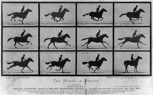 Horse movie image sequence courtesy of the US Library of Congress.
Constraints
The human vision threshold to process a series of images as continuous is about 16 Hz. For computer graphics, that means we have at most 62.5 milliseconds to do the following:- Determine where the eye is looking in a virtual scene.
- Figure out how the scene would look from this angle.
- Compute the colors of the pixels on the display to draw this scene.
- Fill the frame buffer with those colors.
- Send the buffer to the display.
- Display the image.
Basic Graphics Theory
All the World's a Stage
 Painting by the infamous Bob Ross courtesy of deshow.net.
- Determine what the objects in the world look like.
- Determine where the objects are in the world.
- Determine the position of the camera and a portion of the scene to render.
- Determine the relative position of the objects with respect to the camera.
- Draw the objects in the scene.
- Scale the scene to the viewport of the image.
Object Coordinates - Breaking up objects
How do we draw objects on the screen quickly? Computers are really great at doing relatively simple commands a lot of times in succession really fast. So, to take advantage of this, if we were able to represent the whole world with simple shapes, we could optimize graphics algorithms to process a lot of simple shapes really fast. This way, we don't have to make the computer recognize what a mountain or a meadow is in order to know how to draw it. We'll have to create some algorithms to break our shapes down to simple polygons. This is called tessellation. Although we can use squares, we'll probably use triangles. There are lots of advantages to them, such as that all triangle points are co-planar and the fact that you can approximate just about anything with triangles. The only problem we have is that round objects will look polygonal. However, if we make the triangles small enough, like 1 pixel in size, we won't notice them. There are lots of methods on the "best way" to do this and it might depend on the shape you're tessellating.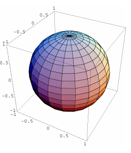
World Coordinates - Putting our objects in the world
We really start our graphics journey here. We define an origin somewhere and every point in the scene is defined by a vector from the origin to that point. Although it's a 3D scene, we'll define each point as a 4-dimensional point \( [x,y,z,w] \), which will map to a 3D point at coordinates \([\frac{x}{w},\frac{y}{w},\frac{z}{w}]\). This kind of mapping is called homogeneous coordinates. There are advantages to using homogeneous coordinates, but I won't discuss them here. Just know we want to use them. A problem presents itself if we want to move around in our scene. If we want to move our view, we can either move the camera to another location, or just move the world around the camera. In the computer, it's actually easier to move the world around, so we do that and let the camera be fixed at the origin. The modelview matrix is a 4x4 matrix that we can use to move every point in the world around and keep our camera fixed at its location. This matrix is basically a concatenation of all the rotations, translations and scaling that we want to do to the scene. We multiply our points in world coordinates by the modelview matrix to move us into what we call viewing coordinates: \[ \left [ \begin{matrix} x \\ y \\ z \\ w \\ \end{matrix} \right ]_{view} = [MV] \left [ \begin{matrix} x \\ y \\ z \\ w \\ \end{matrix} \right ]_{world} \]Viewing Coordinates - Pick what we can see
After we've rotated, translated, and scaled the world, we can select just a portion of the world to consider. This we do by defining a viewing frustrum, or a truncated pyramid. This frustrum is formed by defining 6 clipping planes in viewing coordinates. The idea is that everything outside this frustrum will be clipped, or discarded, when drawing the final image. This frustrum is defined in a 4x4 matrix. The OpenGL glFrustrum() function defined this matrix as follows: \[ P = \left [ \begin{matrix} \frac{2*n}{r-l} & 0 & \frac{r+l}{r-l} & 0 \\ 0 & \frac{2*n}{t-b} & \frac{t+b}{t-b} & 0 \\ 0 & 0 & -\frac{f+n}{f-n} & -\frac{2fn}{f-n} \\ 0 & 0 & -1 & 0 \\ \end{matrix} \right ] \]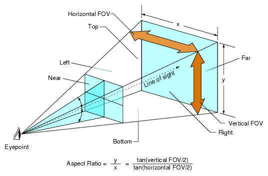 Picture courtesy of Silicon Graphics, Inc.
[MV] \left [ \begin{matrix} x \\ y \\ z \\ w \\ \end{matrix} \right ]_{world} \]
Clip Coordinates - Only draw what we see
This coordinate system is a bit different. These coordinates are left-handed (we've been dealing with right-handed systems up to now) and is such that the viewing frustrum we defined earlier maps to a cube that ranges from (-1,1) in X, Y and Z. Up to now, we've been keeping track of all the points in our scene. However, once we have them in clip coordinates, we can start clipping them. Remember our 4D-to-3D point conversion? If not, we said that \( [x,y,z,w]_{4D} = [\frac{x}{w},\frac{y}{w},\frac{z}{w}]_{3D} \). Because we only want points in our viewing frustrum, we only want to further process points such that \( -1 \le \frac{x}{w} \le 1 \), or \( -w \le x \le w \). This goes for coordinates in Y and Z as well. This is a simple way to tell if points lie inside or outside our view. If we have points inside our viewing frustrum, we do something called perspective divide, where we basically divide by w to move from 4D to 3D coordinates. These points are still in the left-handed clip coordinates, but at this stage, we call them normalized device coordinates.Normalized Device Coordinates - Figure out what obscures what
You can think of this as an intermediate step before mapping to an image. If you think about all the possible sizes of images you could have, we don't want to render for one image size and then either scale and stretch the image or re-render the image to fit in case the size changes. Normalized device coordinates (NDC) are nice because no matter what the image size is, you can scale the points in NDC to your image size. In NDC, you can see how the image will be constructed. The image being rendered will be projections of the objects inside the frustrum on the near clipping plane. Thus, the smaller the coordinate of a point in the Z direction, the closer that point is. At this point, we don't usually do matrix calculations anymore, but apply a viewport transformation. This is usually just to stretch the coordinates to fit the viewport, or the final image size. The last step is to draw the image by converting things to window coordinates.Window Coordinates - Scale objects to canvas
The window is where the image is being drawn. At this point, our 3D world is a 2D image on the near clipping plane. We can use a series of line and polygon algorithms to draw the final image. 2D effects, such as anti-aliasing and polygon clipping, are done at this point before the image is drawn. As well, our window might have different coordinates. For example, sometimes images are drawn with positive X to the right and positive Y downward. A transformation might be needed to draw things correctly in window coordinates.There and Back Again - The Graphics Pipeline
You won't be handling all of the above steps yourself. At some point, you will use a graphics library to define things like the modelview and projection matrices and polygons in world coordinates and the library will do just about everything else we talked about. If you're designing a game, you don't care about how the polygons get drawn, only that they get done correct and fast, right? Libraries like OpenGL and DirectX are very fast and they can use dedicated graphics hardware to do these computations quickly and easily. They are already widely available and there are a large number of developers that use them, so get comfortable with them. They still leave you with a lot of control over how things are done and you'd be amazed at some of the things people can do with them.Conclusion
This is a very simple overview of how things are done. There are many more things that happen at the later stages of the rendering process, but this should be enough to get you oriented so that you can read and understand all the brilliant techniques presented in other articles and in the forums.External Links
If you're interested in reading up on some of the interesting things in this article, I suggest the following sites: http://www.scratchapixel.com/lessons/3d-advanced-lessons/perspective-and-orthographic-projection-matrix/perspective-projection-matrix/ http://www.songho.ca/opengl/index.htmlArticle Update Log
21 Nov 2013: Initial releaseRelated Tutorials

Procedural Generation of 2D Tile Maps in Games
The article explains how to build a procedural 2D cave map generator using cellular automata. It covers map representat…

Localizing A Game Into French — Which Variant Should You Choose?
So, you’re making an awesome indie game, and now you’re thinking about localizing it into French? Great idea! There ar…
 Level Up Translation

How Long Does It Take To Localize An Indie Game?
So you’re planning on localizing your indie game, but you’re not sure how much time to schedule in. While the timing o…
Level Up Translation

Creating game videos: best practices and pitfalls to avoid
Game video production: practical tips on how to create a game trailer or teaser that you can be proud of. Give your aud…
 Alconost

Adopting CI/CD: How Midwinter Entertainment iterates at speed with the help of IMS
Game development was once like one long sprint: a huge effort until you reached the finish line — at which point you co…
 GameDev.net

5 Things to Consider When Making a Video to Promote Your App or Game
How can you show an app or game in your video in a way that attracts new users? Let’s take a look at what to go by when…
Alconost
Discussion
More from Tim Bright

Particle Systems using Constrained Dynamics
A really cool way to simulate large numbers of particles with path constraints *without* using springs.
Tim Bright

Matrix Inversion using LU Decomposition
Need to solve a problem involving matrix inversion? This article is for you!
Tim Bright
Advanced Intersection Test Methods
This advanced article on intersection tests is primarily about curve intersection, but it also contains useful informat…
Tim Bright
Discussion