GameDev.net gamedev.net
🔒 Locked

Spring creation and force calculation

Started by Mystery Aug 22, 2004 at 9:19 PM 97 replies 19.2k views
Original Post
Mystery
Mystery
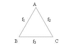
Hi guys, I got confused with some rather basic stuff so will need your help here. I am trying to create 3 springs from the above structure and to calculate the spring force. However, I find that there are quite a number of ways to create them and may end up with different results and thus not consistent. E.g I can create them as 1) A - B, B - C, A - C Resultant force of A = f1 + f2 Resultant force of B = -f1 + f3 Resultant force of C = -f2 - f3 And if I create them this way: 2) B - A, B - C, A - C Resultant force of A = -f1 + f2 Resultant force of B = f1 + f3 Resultant force of C = -f2 - f3 Am I missing out something? The way I am doing the calcution is that I loop through all the springs in each timestep. And for each spring, I calculate the force, assign it to first node and the negated value of the force to the other one.
JesusDesoles
JesusDesoles
In the following prefix 'f' refers to a scalar quantity while 'v' refers to a vector quantity.

For every spring 'i' calculate: fF = fK * ( fLength - fRestLength ), which is positive if the spring wants to contract and negative if the spring wants to expand.

Then for every node 'j' calculate: vF[j] += fF[k] * vDirToneighbour[k], where 'k' goes through all the neighbours of the node j. Set vF[j] to zero before looping through 'k'.

That is, first calculate the force for every spring as a scalar. This scalar holds the information about whether the spring wants to contract or expand in its sign. Then for every node use this information by directing the scalar force towards the respective neighbour.

JD
Mystery
Mystery
Thanks JD. Does that mean what I did earlier was wrong? This is because currently my data structure is such each spring will hold the the pair of node numbers that it is connecting. I believe what you did is each node will know who its neighbours are.

Quote:
Original post by JesusDesoles
In the following prefix 'f' refers to a scalar quantity while 'v' refers to a vector quantity.

For every spring 'i' calculate: fF = fK * ( fLength - fRestLength ), which is positive if the spring wants to contract and negative if the spring wants to expand.

Then for every node 'j' calculate: vF[j] += fF[k] * vDirToneighbour[k], where 'k' goes through all the neighbours of the node j. Set vF[j] to zero before looping through 'k'.

That is, first calculate the force for every spring as a scalar. This scalar holds the information about whether the spring wants to contract or expand in its sign. Then for every node use this information by directing the scalar force towards the respective neighbour.

JD
Mystery
Mystery
On 2nd thought, I think my results from calculation are still consistent since the computation of the force takes into consideration the relative position of the positions of the nodes.(vector)
JesusDesoles
JesusDesoles
The ways to implement a central force network are many. Obviously, the optimizations possible for different implementations vary accordingly.

As it usually is with optimizations the best way is to disregard them at first and make a working implementation which is intuitive. Then after you start optimizing you can compare the outcome of the optimization to the first model. Of course with experience the first draft can be more or less optimized already but it should always be intuitive enough for you to be sure about what is going on.

In your current implementation you have(?) a list of springs that hold references to adjacent nodes. Every spring knows its spring constant and its rest length. The spring can query the positions of the adjacent nodes and calculate the current (compressed or extended) length of itself and can therefore calculate the fF-value.

Since the spring can query the node positions it can also calculate the direction vector between the nodes which can be used to calculate the vF-value for both of the nodes. All that is left for the spring to do then is to call NodeA->AddForce( vF ) and NodeB->AddForce( -vF ). Check the signs so that I haven't messed up here.

I'm also assuming that you're using a spring class and a node class. You don't have to but I have to assume something.

Before any forces are added in respective calculation loops the forces at the nodes have to be zeroed so that you have no leftovers from the previous force-calculating loop. This may be a problem if you don't(?) have any other reference to the nodes except from the springs. Also, after all the forces are gathered at the end of the loop you have to have some way of telling to nodes to calculate their respective acceleration vA = vF/fM, velocity vV += vA * dt (Euler, replace if you're using something more sophisticated) and finally position vPos += vV * dt (Euler again). That, is for every node do something like Node->UpdatePosition().

To sum up:
1. For every node: Node->ZeroForces()
2. For every spring: Spring->UpdateForces()
3. For every node: Node->UpdatePosition( dt )
4. Render and go to 1.

One way to do this is to have a list of nodes and list of springs, where each spring has some reference to two particular nodes in the nodes list. Here the word 'list' refers to a container of your choice be it array, vector, list, or the famous 'whatever'.

I think there are many tutorials on spring networks on the web. The reason why I'm spending time here is that this is what I think people should do first. It is very rewarding to see your first dynamic spring system in action.

Questions? Shoot.

JD

EDIT: I'm not promoting/demoting the particular implementation but take a look at the spring network tutorial at Gamasutra
http://www.gamasutra.com/features/20011005/oliveira_pfv.htm

[Edited by - JesusDesoles on August 23, 2004 5:08:32 AM]
Mystery
Mystery
Thanks JD for taking the time to write such a detailed explanation.

Yes, the system you decribed above is exactly what I am doing now. I have a Particle(node) class and a spring class. The particle class will store stuff like its position, velocity, force, etc. Spring class will store the pair of particles, its rest length, etc.

I am using the Euler method to step through my simulation. At each timestep, I will clear the forces of each node before calculating the external force(Gravity) and internal force(Spring force). My spring force calculation is of what you have described.

This is formula I used for the force calculation:

L - spring vector
l - length of the spring (scalar)
ks - spring constant
kd - damping constant
v1,v2 - velocities of spring's ends
r - rest length of the spring

F = {ks(l-r) + kd[(v1-v2)*L]/l}*L/l

I do remember someone posting a negative sign for the force instead i.e (F = -{ks(l-r) + kd[(v1-v2)*L]/l}*L/l)
(Anyone can confirm which is the right ans)

In any case, I am still unable to get my desired result.
Mystery
Mystery
Quote:
Original post by JesusDesoles

EDIT: I'm not promoting/demoting the particular implementation but take a look at the spring network tutorial at Gamasutra
http://www.gamasutra.com/features/20011005/oliveira_pfv.htm


I have actually read that article several times already in my attempt to solve my current problem. :)
JesusDesoles
JesusDesoles
The negative sign in Hooke F = -k * dx is for notation and basically says that for a stretched spring the force is pulling the spring back to its rest configuration. Whether you should use the negative sign or not depends on your direction vectors, i.e., implementation details. Just make sure that for a stretched spring the force added to a node is directed towards the neighbour and for a compressed spring away from the neighbour. Piece of paper and a debug session with a simple network (use a single triangle with one node initially slightly off from the rest configuration).

At first I suggest you don't do damping.

Just accumulate forces for every node. Then do Euler for the node:

vAcc = vForce/fMass
vVel += vAcc * dt
vPos += vVel * dt
[vVel *= fDamp] <-- Simple damping where fDamp is between 0.0f and 1.0f; 1.0f being no damping. Do no damping at first. Note, that you're not resetting the velocities and positions every frame, just the forces. The velocities and positions are accumulating.

How exactly are you not getting the desired result?

JD
Mystery
Mystery
Yes, I understand that. I did not reset the velocities and the positions, just only the forces at each timestep. I have only set a very low value for the damping constant(0.01). Anyway even I turn it off, it does not help me much.

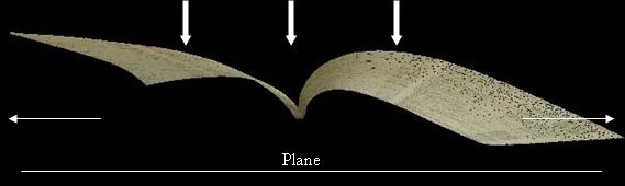
As for my problem, it is best to explain it with the illustration below:


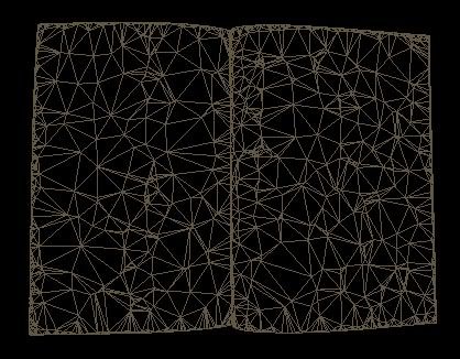
As you might have remembered from my other thread regarding node arrangement, I am trying to flattening the structure seen above. As I applied the gravity force to push it down the plane, I am expecting to spread out as it collides with the plane. However, what is happening in my simulation is that the points simply collapses to the plane with little "spreading" on its sides.
JesusDesoles
JesusDesoles
Note, that for vVel *= fDamp type of damping a low fDamp value means high damping.

Now, let's date your system a bit, i.e., never dump on the first compilation. It may be worth a few rounds before dumping this one and moving onto a system with bending stiffness.

What is your collision response like? Are you sure you're not clamping the nodes every time they hit the ground level? What do you do to a node once it hits the ground?

Once the system seems stable (a wrinkled(?) state for your system) what are the spring lengths? Are they equal to rest lengths or something else?

What happens if you clamp the other side of the system and let the simulation roll? That is, store the initial positions of the leftmost nodes and for every simulation step reset their positions to the initial values. Does the sheet fold down nicely, or what?

Have you checked your simulation using a simple mesh I mentioned earlier?

JD

P.S. I found you a paper for bending stiffness calculations that may be easier to understand than the basic elasticity calculations I mentioned in the other thread. See http://eg04.inrialpes.fr/Programme/ShortPresentation/PDF/short38.pdf. I've just browsed it through and to me it seems to be a long path compared to the standard matrix system but it may be easier to grasp.

[Edited by - JesusDesoles on August 24, 2004 1:48:38 AM]
Mystery
Mystery
I will try to answer some of your questions.

For plane collision, this is what I did. Upon plane collision, the node will have a new velocity vector such that the current velocity vector [v1, v2 ,v3] will become [v1, v2, -kv3] where k for case would be 0.1.

If the node penetrates through the plane, I will restore the system to its previous time, t-1, and calculate a new timestep such that tnew = told/2

Please take a look at this paper (section 3.3.2) -> http://www.dcs.uky.edu/~seales/dli2/iccv-final-01.pdf
I am doing something similar to that.

Yes, the paper will become wrinkled. I supposed the springs will be more compresssed since total surface is reduced. I did an informal check by using a freeware program called - RAPIDFORM which can load OBJ file and determines its surface area. The new OBJ file resulted in a smaller surface area.

I am already using a simpler mesh, subsample from 10,000 to 2000 points. I know it is still quite a lot of points but this is the best I can do with my subsampling program.


Thanks for the link. I will check it out.


Quote:
Original post by JesusDesoles
Note, that for vVel *= fDamp type of damping a low fDamp value means high damping.

Now, let's date your system a bit, i.e., never dump on the first compilation. It may be worth a few rounds before dumping this one and moving onto a system with bending stiffness.

What is your collision response like? Are you sure you're not clamping the nodes every time they hit the ground level? What do you do to a node once it hits the ground?

Once the system seems stable (a wrinkled(?) state for your system) what are the spring lengths? Are they equal to rest lengths or something else?

What happens if you clamp the other side of the system and let the simulation roll? That is, store the initial positions of the leftmost nodes and for every simulation step reset their positions to the initial values. Does the sheet fold down nicely, or what?

Have you checked your simulation using a simple mesh I mentioned earlier?

JD

P.S. I found you a paper for bending stiffness calculations that may be easier to understand than the basic elasticity calculations I mentioned in the other thread. See http://eg04.inrialpes.fr/Programme/ShortPresentation/PDF/short38.pdf. I've just browsed it through and to me it seems to be a long path compared to the standard matrix system but it may be easier to grasp.
JesusDesoles
JesusDesoles
Quote:
Original post by Mystery
For plane collision, this is what I did. Upon plane collision, the node will have a new velocity vector such that the current velocity vector [v1, v2 ,v3] will become [v1, v2, -kv3] where k for case would be 0.1.


A bouncing ball with damping. Ok. You might want to ease the damping constant a bit though. I know they use 0.1 in the paper but humor me, okay, this is for testing. See how your system behaves with different k-values.

Quote:

If the node penetrates through the plane, I will restore the system to its previous time, t-1, and calculate a new timestep such that tnew = told/2


Are you detecting the node vs. plane collision _exactly_? This may be quite hard considering the calculation inaccuracy with floating point numbers.

If you notice a node pass the plane:
1. Reverse the node position backwards until it is slightly above the plane. Slightly above so that floating inaccuracies don't give you the same collision again.
2. Calculate how much time it took for the node to travel inside the plane.
3. v3 -> -kv3
4. Let the node travel in the new direction for the time you got from 2.
NOTE: Do not reverse the whole system - just the roque node.

First make a quick hack:
If you notice a collision for a node do 3. and just set the z-component of the node position slightly above the plane, and go update the next node. Effectively this means that a node hitting the plane slides on it for the rest of the timestep and jumps up on the next timestep. This will give the network extra energy but it may just go unnoticed and you'll see if your problem is nodes sticking to the plane due to inaccurate collision detection/restitution.

Quote:

Please take a look at this paper (section 3.3.2) -> http://www.dcs.uky.edu/~seales/dli2/iccv-final-01.pdf
I am doing something similar to that.

Note, that in the paper they implement shear springs making the network rigid, i.e., made of triangles. If I remember correctly your network has polygons higher than triangles. See below.

Quote:

Yes, the paper will become wrinkled. I supposed the springs will be more compresssed since total surface is reduced. I did an informal check by using a freeware program called - RAPIDFORM which can load OBJ file and determines its surface area. The new OBJ file resulted in a smaller surface area.


The problem here is that your network has polygons higher than triangles. If the network dynamics is modelled as central force only these structures are not rigid, that is, they can deform without any work. Think of a rectangle (no face, just the edges) made of sticks with a hinge at every corner. You can deform that easily even if the sticks are solid. This is a central force network (springs) with infinite spring constant.
 _____         /|       "No work required" by|     |  ->   / |       Amazing ASCII Art(tm)|     |      |  ||_____|      | /             |/

In the image above the edges are (in artistic limits) of same length, yet the area has changed. So, if you want to know if there is tension left in the network at its final state sum up the spring lengths before and after the simulation and compare.

JD

EDIT: You might want to assert that after a collision the node's z-velocity is really positive (pointing upward from the plane) and the z-position is really above the collision detection treshold.

[Edited by - JesusDesoles on August 24, 2004 4:18:36 AM]
Mystery
Mystery
When you said polygons higher that triangles, do you mean having polygons that have more than 3 sides. If so, my structures are also made up triangles.
The OBJ has information containing which 3 vertices in the model form a triangle so I supposed that is what you mean.

Here is the closeup view of part of the structure again:


I will try out some of your suggestions and post the results here ASAP. Thanks for your help.

Quote:
Original post by JesusDesoles


Note, that in the paper they implement shear springs making the network rigid, i.e., made of triangles. If I remember correctly your network has polygons higher than triangles. See below.


The problem here is that your network has polygons higher than triangles. If the network dynamics is modelled as central force only these structures are not rigid, that is, they can deform without any work. Think of a rectangle (no face, just the edges) made of sticks with a hinge at every corner. You can deform that easily even if the sticks are solid. This is a central force network (springs) with infinite spring constant.
 _____         /|       "No work required" by|     |  ->   / |       Amazing ASCII Art(tm)|     |      |  ||_____|      | /             |/

In the image above the edges are (in artistic limits) of same length, yet the area has changed. So, if you want to know if there is tension left in the network at its final state sum up the spring lengths before and after the simulation and compare.

JD

EDIT: You might want to assert that after a collision the node's z-velocity is really positive (pointing upward from the plane) and the z-position is really above the collision detection treshold.
JesusDesoles
JesusDesoles
Yes, I mean quadrangles, pentagons, hexagons, etc. These forms usually emerge in random fibre networks like paper. Now you may wonder why paper is stiff if it indeed has these forms, and the reason is that paper fibres resist bending (and shear for that matter), too. Ofcourse, there is more to paper than the fibres but that is probably beyond your interest in modelling the sheet.

If your network has only triangles you're on the safe side. My notion of those higher polygons came from your original picture in one of your other threads.

Currently, the reason for your sheet crumpling is (most likely) incorrect node collision detection/response (my previous post), too low spring constants, or too high damping. For the spring constant Graham and Geoff gave you a good review in the "Spring constant" thread so I'm not going to spend my time there. I do, however, push you to experiment with these values to see how they affect your system behaviour. Be warned, though, very stiff springs tend to nail Euler to the wall.

JD
Mystery
Mystery
I think I might have made some mistakes in rendering the structure some time ago thus giving the impression of polygons higher than triangles. Apologies.

Quote:
Original post by JesusDesoles

If your network has only triangles you're on the safe side. My notion of those higher polygons came from your original picture in one of your other threads.

Currently, the reason for your sheet crumpling is (most likely) incorrect node collision detection/response (my previous post), too low spring constants, or too high damping. For the spring constant Graham and Geoff gave you a good review in the "Spring constant" thread so I'm not going to spend my time there. I do, however, push you to experiment with these values to see how they affect your system behaviour. Be warned, though, very stiff springs tend to nail Euler to the wall.

JD
Mystery
Mystery
I have tried to vary the spring constant, the value of k for plane collision and even the timestep but it still not working well.

Here are some results:

Original structure:


After flattening using a small spring constant(0.01)


After flattening using a big spring constant(3.0)


My observation:
1) When a small spring constant is used, the structure simply collapses with little spreading on its side. This might be because the spring force generated is not significant enough to keep the particles apart after compression.

2) When a larger spring constant is used, the center portion(near the binding of the book) of the structure becomes unstable resulting in distortion.

3) Varying the k used for plane collision and the size of timestep only result in a shorter/longer time for system to reach its stable state.
JesusDesoles
JesusDesoles
With large spring constants or long timesteps nodes can actually jump across the spring induced potential walls. This is due to node velocity being high compared to the Euler timestep (made a nice ASCII-art of this but it messed up the whole board so I had to delete it). Anyway, this is probably what has happened in the simulation with the spring constant of 3.0.

Also, central force networks simulated in dimensions higher than that of the network can easily fold over themselves. Think of two triangles connected at the edges, a quad, if you prefer. You can, without work, fold the other triangle on top of the other because there is no bending stiffness. Drop your shirt on the floor and see if it spreads across the carpet (if this happens I suggest you leave the room quietly). This may be a problem for your simulation if some parts of your network start folding over each other during the drop or at ground contact.

I think the middle image looks quite good. Can you provide a side view of that?

JD

EDIT: Have you tried playing with the mass of the nodes, i.e., make the network heavier? Alternatively you could just force the node z-components to the ground level and see if sheets starts spreading out.

[Edited by - JesusDesoles on August 25, 2004 8:43:47 AM]
GameCat
GameCat
Your current network will bend very easily, you could essentially fold it completely along a polygon edge without any resistance. You could improve realism (at a computational cost) by adding longer springs that "skip" a node and therefore makes the system resist bending, or you could handle by adding constraints that kick in when the network bends to much (a "dot product constraint" for lack of a better world). The first alternative has the advantage of using the same code you already have and worked well for me in a simple cloth sim I wrote years ago.
JesusDesoles
JesusDesoles
GameCat's proposition will work if you're satisfied with the lower number of nodes than your original aim was (the other thread). You have to calculate the rest length for these new springs as if the triangles spanned by each new spring were already on a flat surface.

JD
Geoff the Medio
Geoff the Medio
Haven't read the whole thread, but it looks like you're trying to model bending of a mesh with springs between adjacent nodes. As suggested by GameCat, this won't work well because the springs you're using only work in one direction... along their axis.

To model bending of paper, you could try GameCat's suggestions of springs that skip nodes, or a dot product restraint.

Another option is to give each node point an orientation vector (probably normal to the paper surface when flat), and attach the linear springs you have no at a particular angle to the orientation vector. Then treat the angle between the spring vector and node point orientation vector in a manner similar to the distance between nodes, in order to generate a tortional spring, that applies a restoring torque to oppose any change in the angle between the orientation of the linear distance springs, and the orentation of the node point. This should give a "paper" that resists bending more like you desire.

Note that more node points with the same tortional spring constant between them would be more bendy than the same size area with fewer nodes points, so you might want to adjust the tortional spring constant by the local or overall density of node points.

Topic Locked

This topic has been locked by a moderator. New replies are not allowed.

Sign in to reply to this topic.