JoeJ said: Traditional raytracing tanks here, because the ray needs to traverse all overlapping models down to the closest intersection. Only after that you know the closest intersection of all models.
To be correct (I know I'm the bugging one!) it's not the ray tracing that fails, or traversal to be speaking - it's failure to find correct (or optimal) spatial or boundary hierarchical tree that would end up in handling this scenario in an efficient way. Or to be fully correct - it is wrongly using multi-level BVHs in such case. When you have object A and object B intersecting each other - and you build separately tree for A, separately tree for B - and then a single top-level would be holding A and B as separate leafs - then you've just murdered efficiency in ray traversal through this.
A proper way would be to handle A and B together as a single tree, and use something efficient for heavily intersecting geometry - like a Kd-tree with full SAH (not bucketed!), or split-SAH BVH (which essentially is the same heuristics, and you kind of mess with BVH and scene due to using spatial splits). Both take quite a long of time to build though, and are somewhat extremely hard to do on GPU tree builder (and yes- transforming any of those objects or deforming would require either rebuild, or refit with same heuristics … that would take much longer time than bucketed SAH BVH or HLBVH for example). At that point you still could descend properly in traversal.
Vilem Otte said: it's failure to find correct (or optimal) spatial or boundary hierarchical tree that would end up in handling this scenario in an efficient way. Or to be fully correct - it is wrongly using multi-level BVHs in such case.
Yes, but we may have no choice. Ofc. we want to use instances of BVH just like we do for geometry as well. Otherwise we have to build too much of BVH at runtime, or we need too much storage for offline BVH.
Personally i realized the advantage of instances much too late. My preprocessing tool merges all geometry and removes overlapping sections. Then it generates a new mesh without self intersections and hidden surface, and also a global BVH. This felt efficient to me. Because no processing or memory is wasted on stuff you can not see or do not need.
But the big downside is that my approach now breaks instancing in general. If you use 10 copies of a column to model a building, the preprocessing tool turns each column into unique geometry requiring memory and storage. So i was not really that smart. : / But maybe i can still turn this into overall advantage…
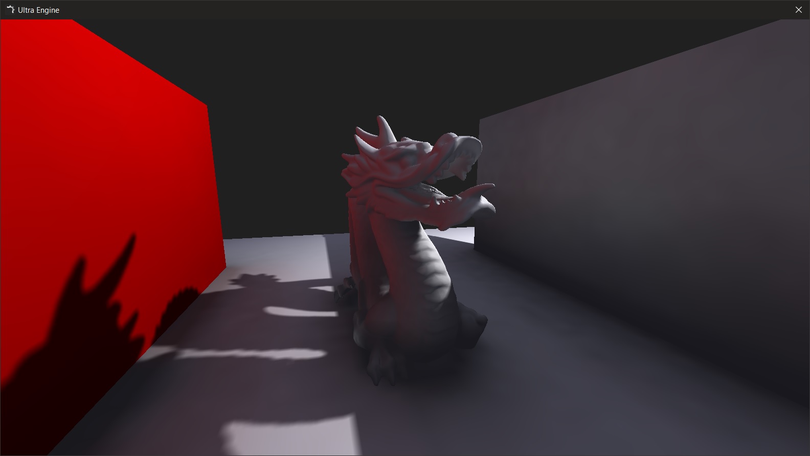
Using a more conventional pathtracing approach for diffuse GI now:
One thing I am struggling with is the idea that blocking 50% of the ray samples with a dark objects in real life does not make the resulting indirect lighting at that spot 50% darker.
In real life, the resulting light in the corner would be maybe 15% darker, definitely not half as bright:
Josh Klint said: In real life, the resulting light in the corner would be maybe 15% darker, definitely not half as bright:
It sounds you include ambient occlusion ideas to your thoughts. But because ambient occlusion is just an invented ‘approximation of GI’, lacking physical background, this never helps. I'm not sure i can follow your thought, but talking if ‘blocked rays’ reminds me on AO.
In reality, those blocked rays hit something which blocks them, and that something then is what is visible to the shading point, and what you want to integrate.
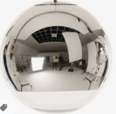
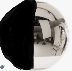
Once i had implemented the Many LODs paper, and this was what made me really understand lighting the easy way. I can explain this model quickly, by making an example using a mirror ball at the shading point:
Imagine we put such small ball on the shading point on the wall. Then we make a photo of the ball. Then we sum up all pixels inside the circle bounding the ball in our photo, and calculate the average by sum / number of taken pixels. This is the incoming light. It's not an approximation, but the exact value we want. To calculate the outgoing light from the shading point, assuming a simple perfect diffuse material of the shading point, we multiply the incoming light with the diffuse aldebo of our material and we are done.
Notice that those 3 sentences contain all the math we need to calculate correct GI. The model is much simpler than other models, like path tracing. All that's left to do is to figure out the math of the kinda fisheye spherical projection we get from making a photo of the ball. Which is the same simple math we use for half sphere environment maps, and it also defines the cosine law for us. Also notice a measurement of distance is not needed. We have replaced this with the concept of solid angle instead. The light source in above photo would become smaller if it were more distant. So it would contribute less to the averaged sum, and thus distance is already handled.
Opposed to path tracing, the model also already includes the idea of a (ir)radiance cache, which we really want for a realtime solution: If we need to calculate above mirror ball, we need to find which parts of the scene are visible to the ball. And to calculate the radiance of the scene we need to create many mirror ball samples on the surface of that scene as well, see we know how the visible surface looks like. We will thus simply cache all our surface mirror ball samples, so we can reuse them. And we get our ‘infinite bounces’ for free this way.
Maybe this model can help you on your way. On your image with the dragon, to me it looks like the green color bleeding on the wall is too much focused on a single spot, like a sharper reflection would be. Maybe ther is something wrong with your math, or maybe you can not integrate the whole halfspace but just a narrower cone, due to taking less samples for perf. reasons.
Josh Klint said: In real life, the resulting light in the corner would be maybe 15% darker, definitely not half as bright:
You can not make an assumption of ‘it should be X % darker’ at all, because if it becomes darker or brighter depends on how bright or dark the blocking wall is. Look at real life corners in rooms. There rarely is a darkening going on, as we would expect from looking at AO CGI images. We do see smooth gradients of changing intensity, and a corner creates a discontinuity to this smooth signal, so we notice that, and we may decide to amplify corners with some AO darkening. But that's just an artistical decision and method. Now imagine we would put a mirror ball int the corner between walls. The mirror ball would woudl show the room on the left side of the image, and a close up of the cornering wall on the right side of the image. So the cornering wall contributes one half of our desired result: 50%. We can say that, but then we still don't know what radiance this 50% have, so we could integrate that.
If your image at that point looked like this, the resulting light at that point would not be halfway between the original and pitch black:
It would be more like 80% the original. I know it should be 50%, but if you try to create this scenario in real life you will see it is not. It may be the way your eye perceives the light, or light bouncing around I'm not accounting for, but the phenomenon I am describing is real and I can't be the first person to notice it.
JoeJ said: All that's left to do is to figure out the math of the kinda fisheye spherical projection we get from making a photo of the ball. Which is the same simple math we use for half sphere environment maps, and it also defines the cosine law for us.
We can derive some raytracing and sampling fundamentals from that. My impression is you may be too sloppy on those details, causing you inaccuracies which might be easy to fix. Your drawing of the yellow rays surely is sloppy. : )
There are actually two ways to do this correctly, if our goal is to integrate incoming light by sending out many rays. Both handle the cosine law in different ways.
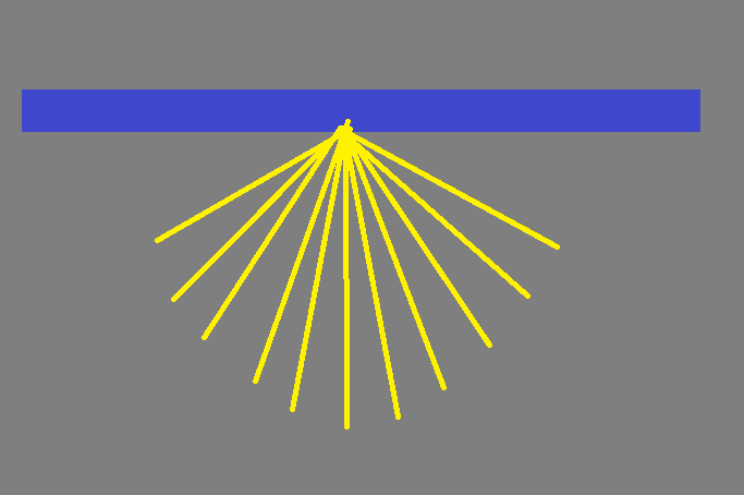
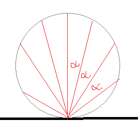
weighted uniform samples:
The ray directions are distributed uniformly, having the same angle alpha between them. To respect the cosine law, we need to weight the radiance of the hitpoint by a factor of dot(ray, surface normal), which gives us the cosine and the circle shape.
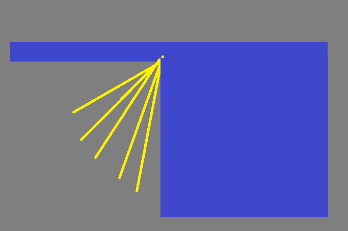
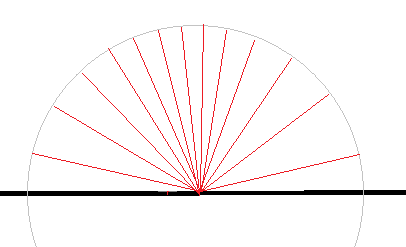
2. Importance sampling:
Here, each sample has a uniform weight of one. To respect the cosine law, we use a non uniform distribution of ray directions instead. So we have more samples along the surface normal, and less samples along the surface plane. This is faster, because we need less rays for the same accuracy.
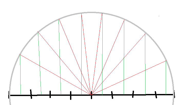
Notice this is also the same math as we see on the spherical mirror ball projection. If we want to trace such mirror ball image, we would do the same thing:
Example spherical environment map image with 8 texels. To get the ray for each texel, we calculate 2D texel distance to image center, then we project the texel upwards so we get a 3D vector of length one (in green). Which gives us the perfect importance sampled distribution of rays (in red).
Josh Klint said: If your image at that point looked like this,
But it would not look like this. The wall wouldn't be black. It would be pretty white. So the final result would end up brighter than expected from imagining a black wall.
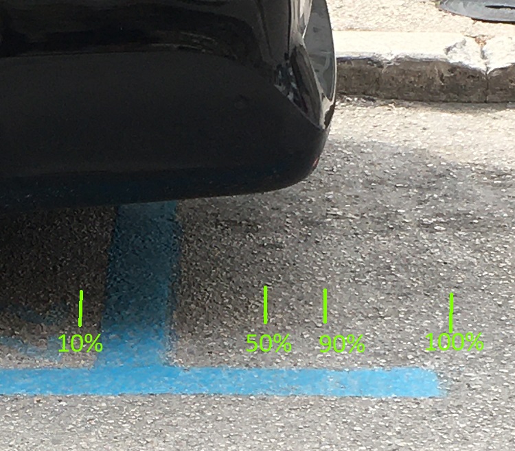
Here's a rough schematic of what I mean. The area directly under where the rear bumper starts is indistinguishable from the area not covered by the car. My 50% mark is probably way too far to the right:
This is probably caused by light bouncing off the road, onto the undercarriage, and back. What's a good way to approximate this without running a million light bounces? I'm thinking some kind of weighted average, like the average of the top 50% or even calculate a standard deviation?
Josh Klint said: This is probably caused by light bouncing off the road, onto the undercarriage, and back.
That's a small factor i think. The larger factor is the light coming in from the sides, which are not occluded by the car. This side way light will contain a lot of reflected sun and sky light, as we look at a bright day scene.
But i still don't really get what you ask for. It could be you're wondering about some inaccuracies, like caused from capturing such side ways light. Or it could be you want to add some AO effect to your GI, maybe to capture more detail with AO than what you get from coarse GI.
Josh Klint said: What's a good way to approximate this without running a million light bounces? I'm thinking some kind of weighted average, like the average of the top 50% or even calculate a standard deviation?
This really sounds what you ask for is what AO already tries to handle as well? If you want to include the factor of skylight, such extensions to AO became pretty popular recently, under the term ‘Directional (Ambient) Occlusion’.
Hi guys i am about to explore this topic as well, I see that you voxelize on cpu, isn't it too expensive ? how do you trace light still in cpu ? and in the case its not, how do you send all the voxel data to the gpu ?