Advertisement

How to Resolve This Normal Issue?

Started by February 12, 2025 10:22 AM
8 comments, last by isu diss 2 days, 20 hours ago

Hi fellas,

Good day!

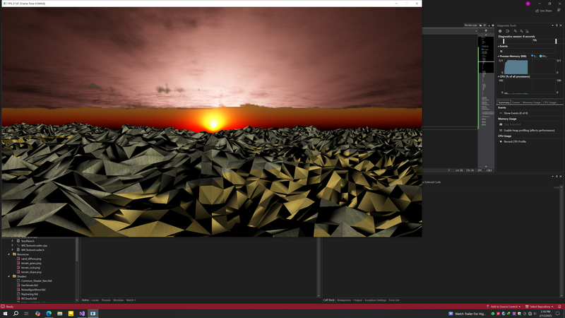
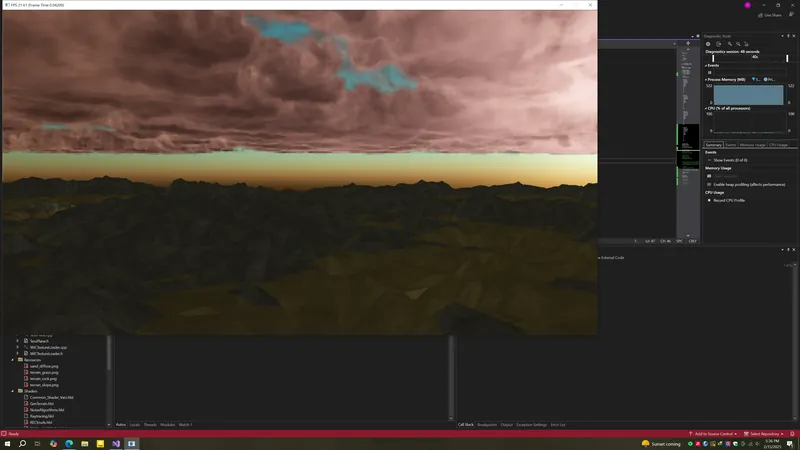
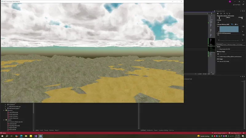
I'm trying to generate a terrain dynamically using perlin noise. In order to do so, I have created a plane and fed into tessellation stages to be tessellated and retrieved the the output via streamout and fed into compute shader to generate height field and fed back into dxr to be raytraced. The problem is the shading, I use diffuse lighting for a start. This dxr setup had worked before(without using tessellation just feed raw geometry directly to dxr) I utilized the rasterization pipeline to facilitate my desired result(generating terrain dynamically). After all these things, I've got everything I needed to shade in dxr, the problem is normals, they seem to have a problem. Any thoughts on to resolve this?

#define HLSL
#include "NoiseAlgorithms.hlsl"

struct RE_VERTEX
{
    float3 Position;
    float2 TextureCoordinate;
    float3 Normal;
};

StructuredBuffer<RE_VERTEX> inVertices : register(t0);
RWStructuredBuffer<RE_VERTEX> outVertices : register(u0);

[numthreads(1, 1, 1)]
void ComputeTerrain(uint3 DTID : SV_DispatchThreadID)
{
    RE_VERTEX inVertex = inVertices[DTID.x];
    RE_VERTEX inVertex2 = inVertices[DTID.x + 1];
    RE_VERTEX inVertex3 = inVertices[DTID.x + 2];

    uint seed = 100000;
    uint3 txDim = uint3(1024, 150, 1024);

    float perlinY = Perlin3D(
        float(inVertex.Position.x),
        float(inVertex.Position.y),
        float(inVertex.Position.z),
        float(txDim.x),
        float(txDim.y),
        float(txDim.z),
        8.0f,
        0.5f,
        4.0f,
        true,
        seed + 50
    );

    float perlinY2 = Perlin3D(
        float(inVertex2.Position.x),
        float(inVertex2.Position.y),
        float(inVertex2.Position.z),
        float(txDim.x),
        float(txDim.y),
        float(txDim.z),
        8.0f,
        0.5f,
        4.0f,
        true,
        seed + 50
    );

    float perlinY3 = Perlin3D(
        float(inVertex3.Position.x),
        float(inVertex3.Position.y),
        float(inVertex3.Position.z),
        float(txDim.x),
        float(txDim.y),
        float(txDim.z),
        8.0f,
        0.5f,
        4.0f,
        true,
        seed + 50
    );

    RE_VERTEX outVertex = (RE_VERTEX) 0;
    outVertex.Position = inVertex.Position;
    outVertex.Position.y = perlinY * 150.0f;
    outVertex.TextureCoordinate = inVertex.TextureCoordinate;

    RE_VERTEX outVertex2 = (RE_VERTEX) 0;
    outVertex2.Position = inVertex2.Position;
    outVertex2.Position.y = perlinY2 * 150.0f;
    outVertex2.TextureCoordinate = inVertex2.TextureCoordinate;

    RE_VERTEX outVertex3 = (RE_VERTEX) 0;
    outVertex3.Position = inVertex3.Position;
    outVertex3.Position.y = perlinY3 * 150.0f;
    outVertex3.TextureCoordinate = inVertex3.TextureCoordinate;


    float3 normal1 = normalize(cross(outVertex2.Position - outVertex.Position, outVertex3.Position - outVertex.Position));
    float3 normal2 = normalize(cross(outVertex3.Position - outVertex2.Position, outVertex2.Position - outVertex.Position));
    float3 normal3 = normalize(cross(outVertex.Position - outVertex3.Position, outVertex2.Position - outVertex3.Position));

    // Calculate avg normals
    float3 avgNormal = normalize((normal1 + normal2 + normal3) / 3);

    outVertex.Normal = avgNormal;
    outVertices[DTID.x] = outVertex;
    
    outVertex2.Normal = avgNormal;
    outVertices[DTID.x+1] = outVertex2;
    
    outVertex3.Normal = avgNormal;
    outVertices[DTID.x+2] = outVertex3;
}


isu diss said:

float3 normal1 = normalize(cross(outVertex2.Position - outVertex.Position, outVertex3.Position - outVertex.Position)); float3 normal2 = normalize(cross(outVertex3.Position - outVertex2.Position, outVertex2.Position - outVertex.Position)); float3 normal3 = normalize(cross(outVertex.Position - outVertex3.Position, outVertex2.Position - outVertex3.Position)); 

// Calculate avg normals 
float3 avgNormal = normalize((normal1 + normal2 + normal3) / 3);

That's overcompiocated. When you calculate a normal from 3 points (or 2 vectors) on a plane, order only affects if it goes inwards or outwards, but not it's line direction or magnitude.
So no need for an average. You can just use one of those 3 normals, as they should be all the same.
(Average is needed only for vertex normals, where we have multiple different normals from adjacent faces.)

That's probably not the reason of your problem, though.

isu diss said:
In order to do so, I have created a plane and fed into tessellation stages to be tessellated and retrieved the the output via streamout and fed into compute shader to generate height field and fed back into dxr to be raytraced.

Wow, what a ride. So that's how you guys work around the limitations of raytracing. /:D\

Advertisement

The answer turned out not to be a bug in DXR at all but rather how the normals were being computed. In our case the problem was that we were taking three vertices (from the stream–output of tessellation) and computing three different cross products with inconsistent ordering. For example, notice that one of the cross products uses

hlsl

Copy

float3 normal2 = normalize(cross(outVertex3.Position - outVertex2.Position, outVertex2.Position - outVertex.Position));

If you work through the math, you’ll see that this (with the way the vertices are read in) is essentially the negative of the “correct” normal computed as

hlsl

Copy

float3 normal1 = normalize(cross(outVertex2.Position - outVertex.Position, outVertex3.Position - outVertex.Position));

Averaging a vector with its negative (or near–negative due to floating–point error) leads to bad results. In our case, even though the average of the three computed normals mathematically should yield the same as normal1 (if computed exactly), in practice the inconsistent ordering (and perhaps even the assumption that three sequential vertices form a triangle) was causing the normals to be off.

What to Do

  1. Use a Consistent Winding Order:
    Pick one way to compute your triangle normal – for example:

    hlsl

    Copy

    float3 triangleNormal = normalize(cross(outVertex2.Position - outVertex.Position, outVertex3.Position - outVertex.Position));

    Then assign that same normal to all three vertices of the triangle. This avoids the ambiguity that comes from averaging differently–ordered cross products.

  2. Compute Normals from the Height Field (Optional):
    If you want smooth shading over a grid (rather than flat shading per triangle), you might consider computing the normal at each vertex using the differences in height between neighboring vertices (i.e. using central differences). For example, if your height field is stored in a 2D grid, then for a vertex at (x,z)(x,z)(x,z) you could do something like:

    h

    Copy

    float heightL = GetHeight(x - 1, z); float heightR = GetHeight(x + 1, z); float heightD = GetHeight(x, z - 1); float heightU = GetHeight(x, z + 1); float3 normal = normalize(float3(heightL - heightR, 2.0, heightD - heightU));

    This produces a smooth normal that represents the slope of the terrain.

  3. Verify Your Geometry:
    Ensure that the streamed–out vertices are indeed laid out as triangles. Tessellation and stream–out can sometimes change the expected order. If the vertices are not in triangle–list order, then reading three at a time may produce degenerate or mis–ordered triangles.

In Summary

The incorrect shading was due to the way the normals were being computed. By using an inconsistent vertex order (and thus some cross products producing normals with reversed directions), the average ended up being wrong. The fix was to compute the triangle normal using a consistent winding order (or better yet, compute normals based on the grid height field so that shared vertices have a proper averaged normal). Once that was done, diffuse lighting in DXR worked as expected.

Thanks fellas for posting your thoughts on this as this is an urgent project for my degree. I like smoke_1's point 2. I'm too trying to generate the height field(per vertex) in that compute shader while generating the normals as well. This SRV is a dimension_buffer. how can i get the height value?

Also if i pass float3(0,1,0) as the normal in the CS. then it reveals there's no winding order issue as terrain gets rendered nicely(of course without nice shadowy areas). problem is the normal generation?

I didn't try what you guys said yet.

isu diss said:
I'm too trying to generate the height field(per vertex) in that compute shader while generating the normals as well.

Yeah, to avoid the need of using so many shader stages, generating all vertex data in a single compute shader sounds like a good idea.
But there is a problem: By doing so, you can't use tessellation shaders anymore. Or you do, but using the compute generated high resolution mesh only for raytracing, while using a low res base mesh with tessellation shaders for rasterization.

The problem is: Raytracing does not support tessellation or mesh shaders, so they become somewhat useless. Which is quite funny, because NV has introduced mesh shader and raytracign at the same time!
They also proposed an Optix alike API for RT, which Microsoft has adopted without spending a thought on it.
The resulting current situation is:
* Raytracing is fundentally broken. Because BVH is blackboxed, there is no way for dynamic geometry as required for any fine grained LOD solution, like Nanite for example. So thankes to raytracing, LOD is now inpossible to solve for us.
* The graphics pipline is fundamentally broken too, because nice things like mesh shaders do not work with the future of graphics: raytracing. And we also have a lot of redunant crap now, like tessellation shaders which are inferior to mesh shaders and thus should be actually removed, assuming that mesh shaders would be a proper and final solution to those geometry problems.
* With so many useless / redundant shader stages around on GPUs these days, it is now very hard compete on the GPU market. Just look at all the driver problems companies such as Intel or Moore Threads have. AMD struggles too. Their RT is just a hack, and their mesh shaders are buggy.

So we have a monopoly driven from false innovation, and costs of GPUs are twice as high as the actual value of such HW.
Thanks for that, and the new leather jacket is really cool and shiny. >:/

But maybe i'm not fair. I mean, NV hs recently shown a solution to the RT geometry problem. They call it Mega Geometry.
You can use it with NVAPI - it's proprietary of course. So they solve the problem they have created in aproprietary way, meaning the fix to the damage they have done only works on NV HW.
And still they have the nerves to call this ‘open source’, proposing other IHVs can join and implement it too! Yeah… maybe after hell freezes over.
A don't need an AI assistant to detect the patterns here.

That said, it's hopeless. But those are your current options:

Generate high res mesh in compute and don't use tessellation - at some point they will deprecate this anyway. As a replacement for the smoothing achieved from tessellation shaders you could use a higher order texture filter, e.g. 4x4 cubic filter which can be done using 4 bilinear lookups. Shadertoy has code.

Or keep doing the wild ride you currently do, which i assume is much slower.

Or do the right thing and boycott RT until they fix it DirectX / Vulkan. But seems the industry already took the bait - RT is mandatory now, so we need to use it to compete all those other fools. Can't wait on the next big thing after that, which is replacing in game characters with AI faces looking like AI porn, it seems. Disgusting.

What a stinking pile of dogshit this is. Ridiclous and stupid, only here to get to the next Video Game Crash some years sooner and having only one GPU vendor remaining.

Ah well, back on topic…

isu diss said:
Also if i pass float3(0,1,0) as the normal in the CS. then it reveals there's no winding order issue as terrain gets rendered nicely(of course without nice shadowy areas). problem is the normal generation?

Winding order and such topics may be involved, but this here is a bit vague:

Smoke_1 said:
in practice the inconsistent ordering (and perhaps even the assumption that three sequential vertices form a triangle) was causing the normals to be off.

Taking your code of averaging 3 normals from all 3 edge pairs of a triangle as example, notice that only one thing can go wrong: They may point inwards instead outwards, but their line direction should be always right. (With ‘line direction’ i mean the two vectors (-1,-1,-1) and (1,1,1) lie on the same line, even if their direction goes in opposite ways.)
This holds no matter how many of our 3 normals go in the wrong direction. No matter if 1, 2, or 3 are wrong, the resulting average line direction is always the same and correct.
And i assume, using tessellation stage ouput, winding order is consistent from there, decreasing chances this is the culprit.

If you can't figure out quickly, i would take the time to visualize the normals. Then you see if they are randomly off, or if just some of them go in the wrong direction. This should help to find the true reason.

If you can't figure out quickly, i would take the time to visualize the normals. Then you see if they are randomly off, or if just some of them go in the wrong direction. This should help to find the true reason.

I'll try to visualize them. thanks.

thank you @joej sir for your info on current RT landscape. this project is for my 2nd degree and i'm running out of time.

Advertisement
    RE_VERTEX inVertex = inVertices[DTID.x];
    RE_VERTEX inVertex2 = inVertices[DTID.x + 1];
    RE_VERTEX inVertex3 = inVertices[DTID.x + 2];
    RE_VERTEX inVertex4 = inVertices[DTID.x + 3];

    uint seed = 100000;
    uint3 txDim = uint3(1024, 150, 1024);

    float perlinY = Perlin3D(
        float(inVertex.Position.x),
        float(inVertex.Position.y),
        float(inVertex.Position.z),
        float(txDim.x),
        float(txDim.y),
        float(txDim.z),
        8.0f,
        0.5f,
        4.0f,
        true,
        seed + 50
    );

    float perlinY2 = Perlin3D(
        float(inVertex2.Position.x),
        float(inVertex2.Position.y),
        float(inVertex2.Position.z),
        float(txDim.x),
        float(txDim.y),
        float(txDim.z),
        8.0f,
        0.5f,
        4.0f,
        true,
        seed + 50
    );

    float perlinY3 = Perlin3D(
        float(inVertex3.Position.x),
        float(inVertex3.Position.y),
        float(inVertex3.Position.z),
        float(txDim.x),
        float(txDim.y),
        float(txDim.z),
        8.0f,
        0.5f,
        4.0f,
        true,
        seed + 50
    );
    
    float perlinY4 = Perlin3D(
        float(inVertex4.Position.x),
        float(inVertex4.Position.y),
        float(inVertex4.Position.z),
        float(txDim.x),
        float(txDim.y),
        float(txDim.z),
        8.0f,
        0.5f,
        4.0f,
        true,
        seed + 50
    );
    
  RE_VERTEX outVertex = (RE_VERTEX) 0;
    outVertex.Position = inVertex.Position;
    outVertex.Position.y = perlinY * 150.0f;
    outVertex.TextureCoordinate = inVertex.TextureCoordinate;
  
    float3 normal = normalize(float3(abs(perlinY - perlinY3), 2.0, abs(perlinY2 - perlinY4)));
    
    if (dot(normal, float3(0,1,0)) < 0.0f)
        normal *= -1;
    
    outVertex.Normal = normal;
    outVertices[DTID.x] = outVertex;

I don't have the information about the height field grid. since this shader technically builds one. this is what I did. it seems to work but still there are artifacts noticeable. here are some snaps.


You should use lower frequency noise to judge normals. Currently it's too spiky. If it's round and smooth you can see much better if normals are right.

isu diss said:
float3 normal = normalize(float3(abs(perlinY - perlinY3), 2.0, abs(perlinY2 - perlinY4)));

Reading the code i assume you calculate 4 heights at corners forming a quad:

1 2
3 4

And you calculate a normal from it's diagonals 1-4 and 3-4.
But this does not map to x and z axis but to diagonals, so the normals are rotated 45 degrees and wrong, i guess.
A correct way would be (assuming y is up):

vec3 quad1 = vec3(0,perlinY,0);
vec3 quad2 = vec3(1,perlinY2,0);
vec3 quad3 = vec3(0,perlinY3,1);
vec3 quad4 = vec3(1,perlinY4,1); // i'm ignoring a scaling factor so xz plane and yup from noise match in size

vec normal = normalize(cross(quad4-quad1, quad3-quad2)); // not sure about sign; maybe you need to negate one vector

This can be optimized, but it should work.
(You may have confused this with classic gradient calculation wher we have this shape:
1
2 x 3
4
Then your approach would be right)

There should be no abs() here, and also no direction check along the global up axis!
That's all just hacks to compensate the wrong math. ; )

isu diss said:
outVertex.Position.y = perlinY * 150.0f;

Notice the normal we have just calculated comes from the 4 corners of our quad.
Thus the normal matches a point in the center of the quad, not so well the first corner.
So probably you want to use the average of all 4 points:

outVertex.Position.y = (perlinY + perlinY2 + perlinY3 + perlinY4) * 0.25f * 150.0f;

It's maybe a problem you calculate normals per quad, but in the end you need to cut it into 2 triangles.
The easiset way to deal with this may be switching to vertex normals instead using polygon normals.

In short: One off and half off errors everywhere. Yeah, i hate this too. :D

uint Stride = DTID.x * 6;
RE_VERTEX inVertex1 = inVertices[Stride + 0];
RE_VERTEX inVertex2 = inVertices[Stride + 1];
RE_VERTEX inVertex3 = inVertices[Stride + 2];
RE_VERTEX inVertex4 = inVertices[Stride + 3];
RE_VERTEX inVertex5 = inVertices[Stride + 4];
RE_VERTEX inVertex6 = inVertices[Stride + 5];

/*

Winding Order in Plane.RE3DM(my own file format)

inV4| /|inV2
| / |
inV3|/ |inV1

inVertex1
inV1 > Position: -112 -2.84217e-014 -128
Normal: 0 1 -2.22045e-016
TextureCoordiate: 0.0625 1

inVertex2
inV2 > Position: -112 -2.4869e-014 -112
Normal: 0 1 -2.22045e-016
TextureCoordiate: 0.0625 0.9375

inVertex3
inV3 > Position: -128 -2.84217e-014 -128
Normal: 0 1 -2.22045e-016
TextureCoordiate: 0 1

inVertex4
inV3 > Position: -128 -2.84217e-014 -128
Normal: 0 1 -2.22045e-016
TextureCoordiate: 0 1

inVertex5
inV2 > Position: -112 -2.4869e-014 -112
Normal: 0 1 -2.22045e-016
TextureCoordiate: 0.0625 0.9375

inVertex6
inV4 > Position: -128 -2.4869e-014 -112
Normal: 0 1 -2.22045e-016
TextureCoordiate: 0 0.9375


*/
Before tessellation, this plane will be the input (i convert re3dm from fbx exported from maya). Thought of sharing. since I decided to check again

Advertisement